Exploded View
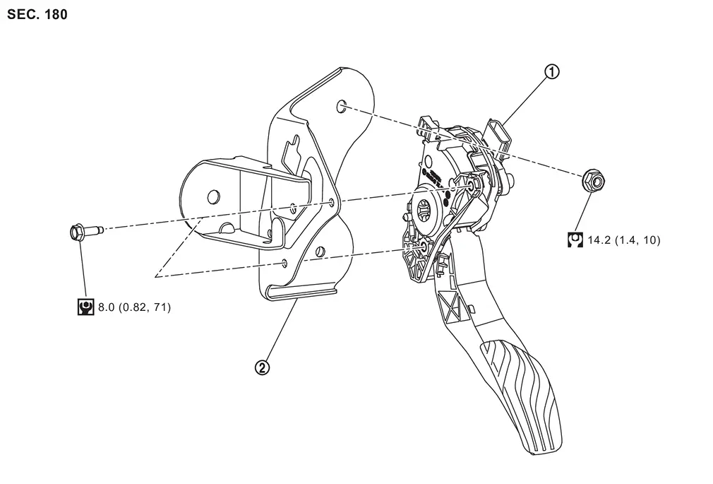
 |
Accelerator pedal assembly |  |
Accelerator pedal bracket | ||
 |
: N·m (kg-m, ft-lb) | ||||
 |
: N·m (kg-m, in-lb) |
Removal and Installation
REMOVAL
CAUTION:
-
Never disassemble accelerator pedal assembly.
-
Never remove accelerator pedal position sensor from accelerator pedal assembly.
-
Avoid impact from dropping etc. during handling.
-
Be careful to keep accelerator pedal assembly away from water.
Disconnect accelerator pedal harness connector as follows.Slide the connector lock to  upward (1).
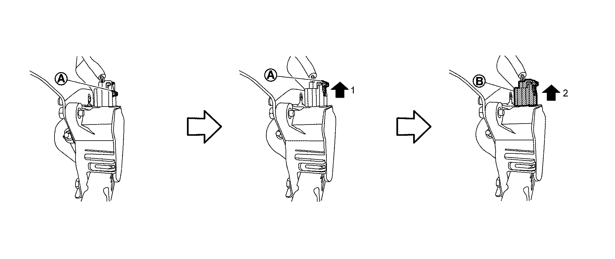
 to upward (2) with pushing in the connector lock.
Remove the mounting bolts, and remove accelerator pedal assembly.
If necessary remove mounting nut, and remove accelerator pedal bracket.
INSTALLATION
Note the following, and install in the reverse order of removal.
-
Install the protrusion
of the bracket into the locating hole of the accelerator pedal assembly before tightening the accelerator pedal assembly mounting bolts.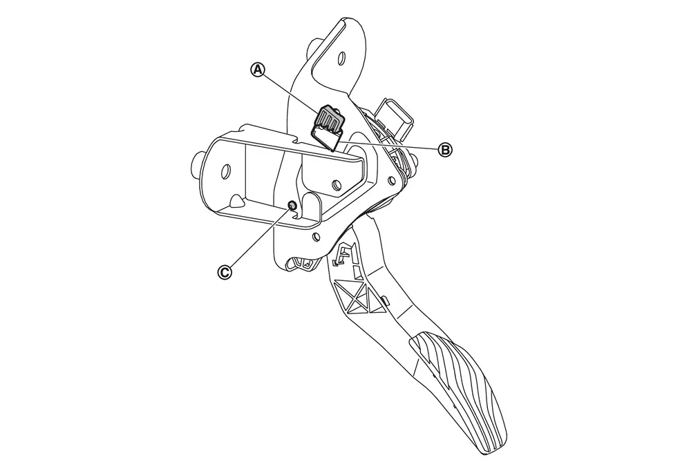

: Locating pin CAUTION:
-
When inserting accelerator pedal assembly to protrusion
, never scratch locating hole with the protrusion. -
Tighten bolts with the locating pin
securely inserted in the bracket hole.
-
CAUTION:
When harness connector of accelerator pedal position sensor is disconnected, perform “ACCELERATOR PEDAL RELEASED POSITION LEARNING”. Refer to Work Procedure.
Inspection
INSPECTION AFTER INSTALLATION
-
Check accelerator pedal moves smoothly within the whole operation range when it is fully depressed and released.
-
Check accelerator pedal securely returns to the fully released position.
 NOTE:
NOTE:
For the electrical inspection of accelerator pedal position sensor. Refer to Component Inspection.
Other materials
Additional Service When Replacing Third Seat Control Unit Lh
Description
When after replacing third seat control unit LH, third seat LH position initialization must be performed. For details, refer to Work Procedure.
Work Procedure
REPLACE THIRD SEAT CONTROL UNIT LH
Replace third seat control unit LH. Refer to Removal and Installation.
>>
GO TO 2.
TH ...
Folding Switch
Removal and Installation
REMOVALRemove luggage side lower finisher RH. Refer to Removal and Installation.
Disengage fixing pawls and then remove folding switch.
: Pawl
INSTALLATIONInstall in the reverse order of removal. ...
Engine Coolant
Service Data
ENGINE COOLANT CAPACITY (APPROXIMATELY)Unit: ℓ (US qt, Imp qt) Engine coolant capacity [With reservoir tank (“MAX” level)]
13.0 (13-6/8,11-4/8)
Reservoir tank engine coolant capacity (At “MAX” level)
1.61 (1-6/8,1-3/8)
...