
Nissan Armada 2025-2026 Service and Repair Manual: Work Procedure
Description
Calibration must be performed after replacing or removing/installing the following parts..
Head Up Display unit
Windshield glass
Steering member
Diagnosis Procedure
 NOTE:
NOTE:
Place the vehicle on level ground.
Keep the space when calibration. (Vehicle front area)
Wide: 2.0 m (6.56 ft)
Height: 2.0 m (6.56 ft)
Length: 2.0 m (6.56 ft)
TARGET PREPARATION
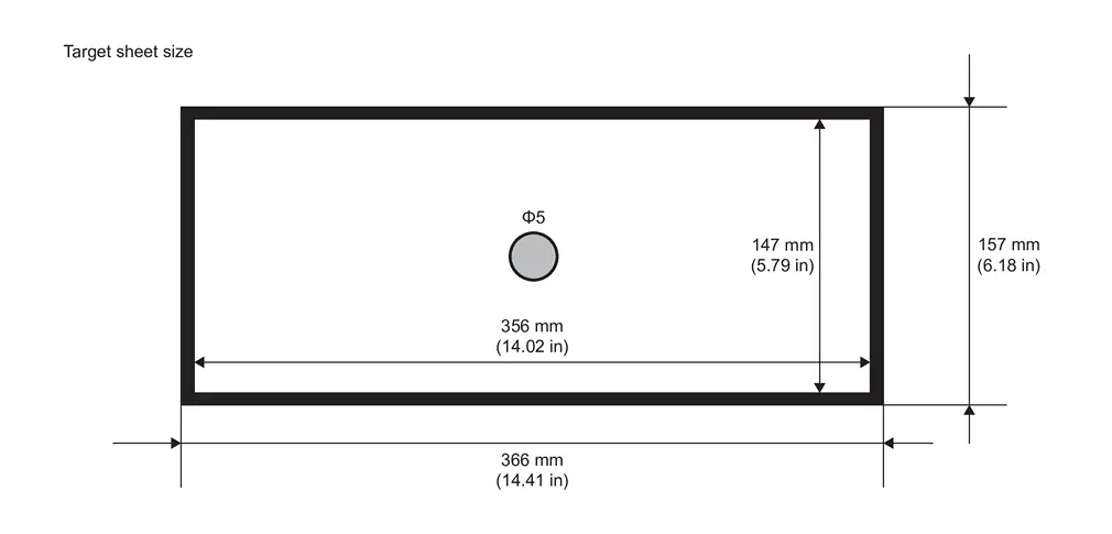
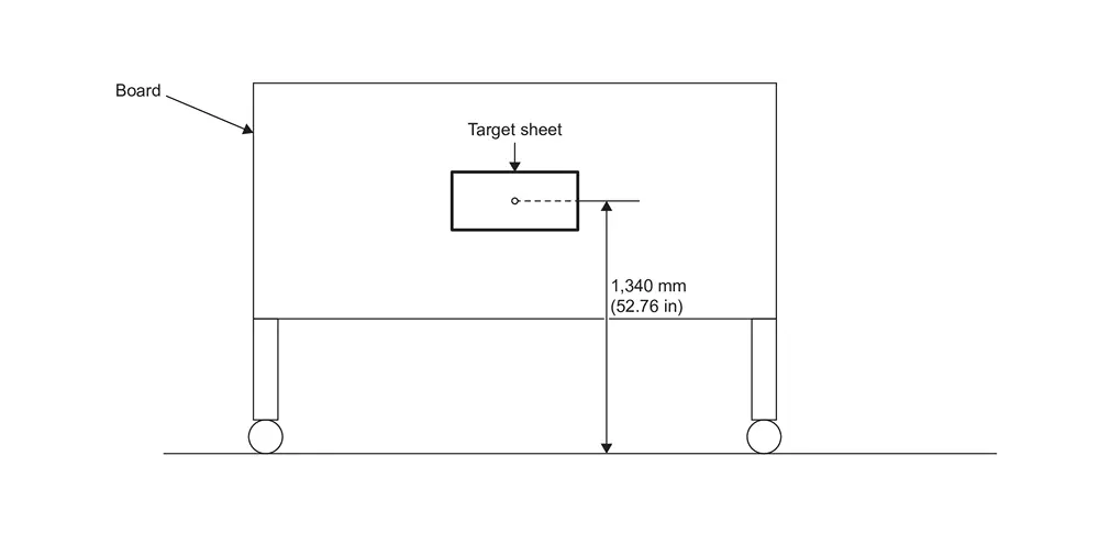
Prepare the distortion calibration jig according to the following procedure and the figure.
Prepare target sheet according to the figure.
Paste the created target sheet onto the board according to the figure.
GO TO 2.
TARGET SETTING
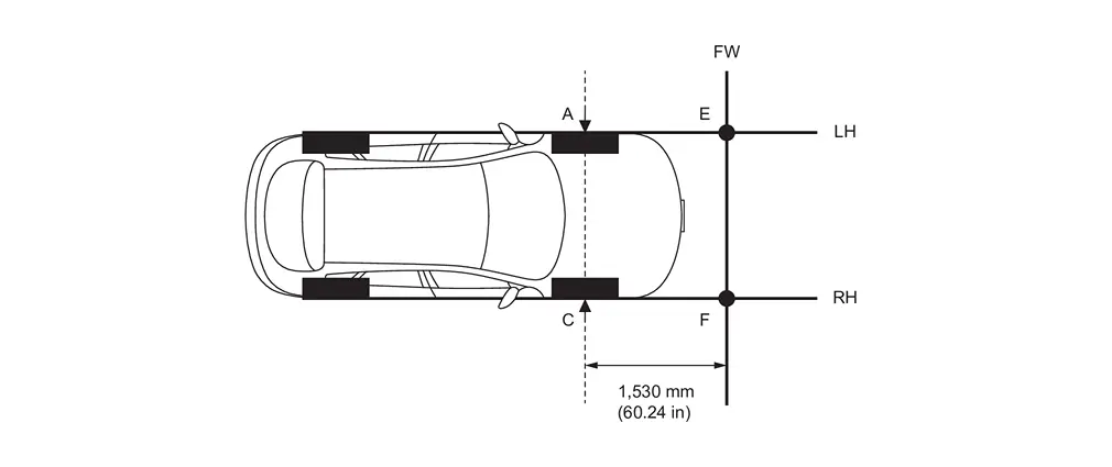
Mark points “A�, “B�, “C� and “D� at the center position of each wheels.
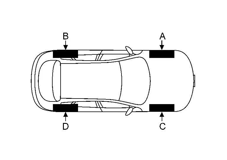
Draw line "LH (RH)" passing through points "A (C)" and "B (D)" on the left (right) side of vehicle.
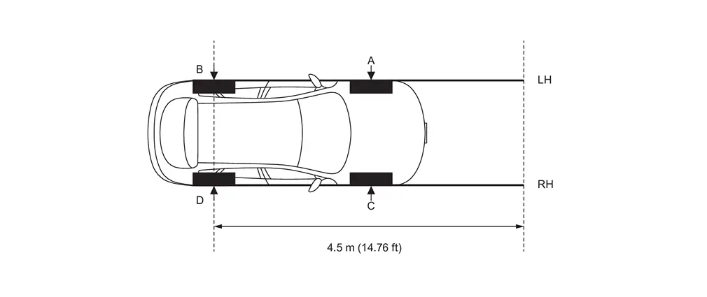 NOTE:
NOTE:Approximately 4.5 m (14.76 ft) or more from the point "B (D)".
Mark point "E (F)" on the line "LH (RH)" at the positions 1,530 mm (60.24 in) from point "A (C)". And then draw line "FW" passing through the points "E" and "F".
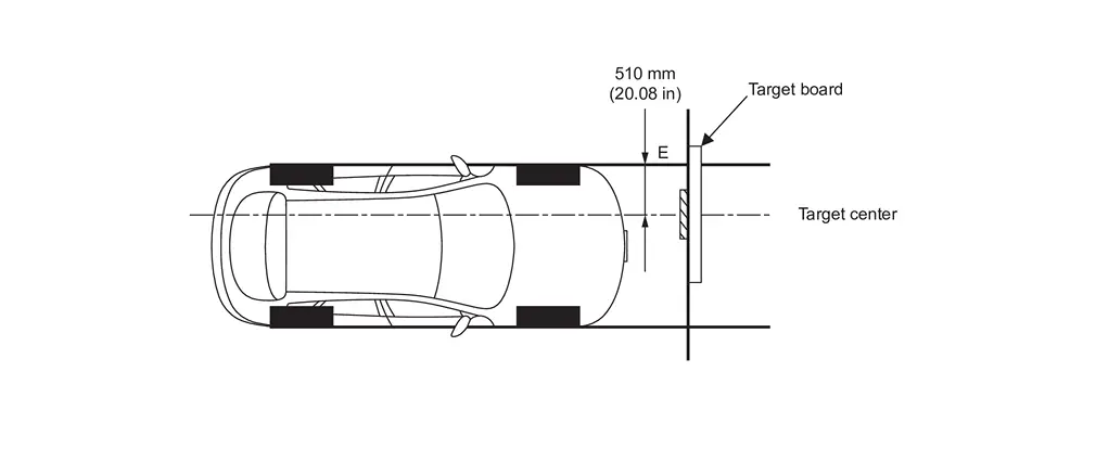
Place the target board on the line "FW" so that the center of the target comes to 510 mm (20.08 in) from mark point "E".
GO TO 3.
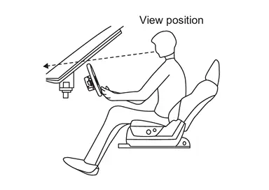
DRIVER'S SEAT POSITION ADJUSTMENT
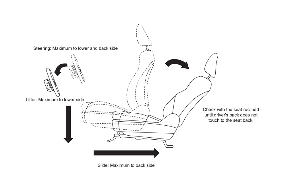
Adjust the driver's seat and steering wheel to the position shown in the figure.
GO TO 4.
RESET OPERATION
Turn ignition switch ON.
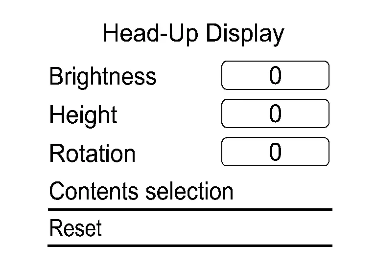
Touch "Reset" on the Head Up Display setting screen of the combination meter and reset the setting. Refer to Switch Name and Function.
GO TO 5.
TARGET CENTER POSITION ADJUSTMENT
 With CONSULT
Select "Distortion calibration" of "Work Support" on "Head Up Display� using CONSULT.
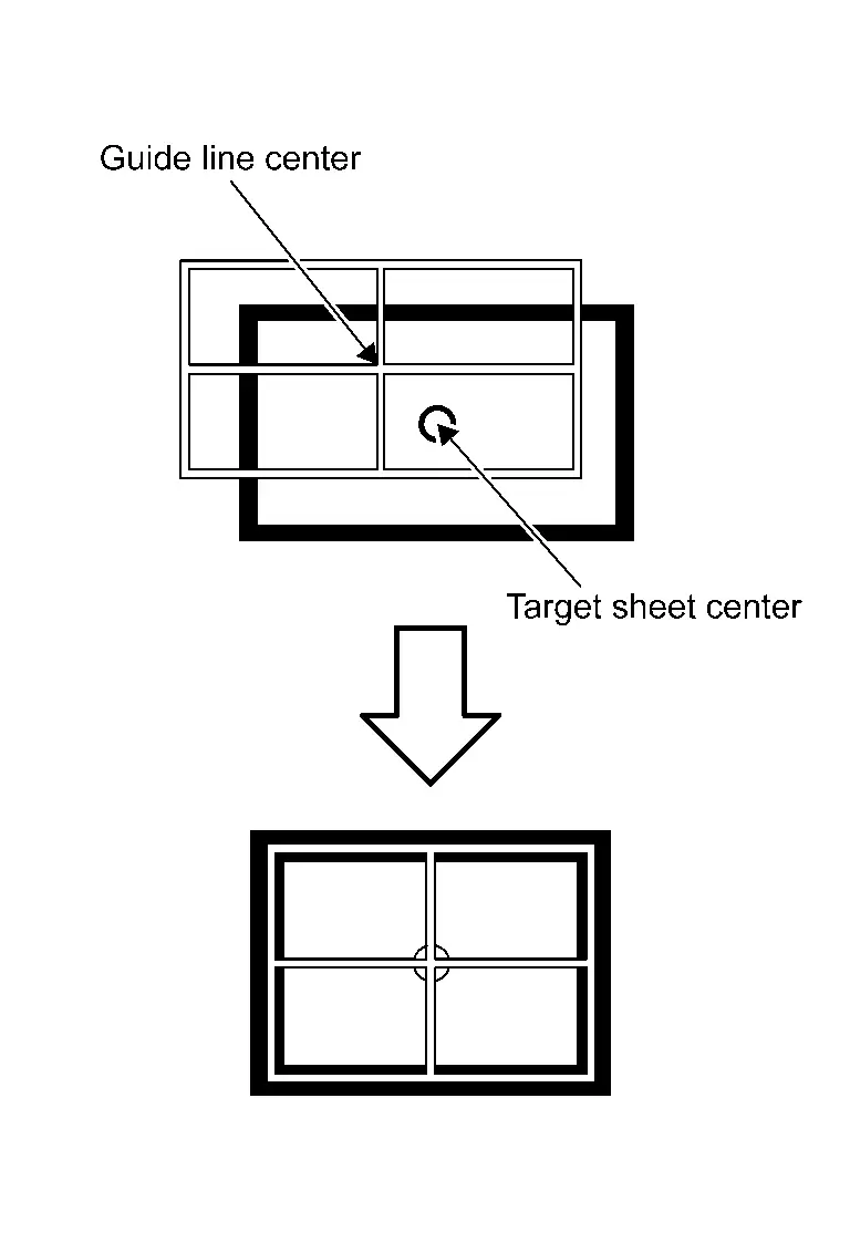
Confirm from the driver's seat whether the center position of the displayed guideline is coincident with the center position of the target sheet.
NOTE:
If there is a gap between the center of the guideline and the target sheet,do not change the vehicle position, and match the center point by moving the target seat and target seat up and down, back and forth with setting the design standard dimension as a basic point.
GO TO 6.
PERFORM DISTORTION CALIBRATION
With CONSULT
Visually check for the distortion of the guideline from the standard HUD design view-point (Refer to 5-2).

If the guideline display is distorted, touch "+" or "-" of the item corresponding to the distortion type to be corrected according to following table, and calibrate to match the target sheet.
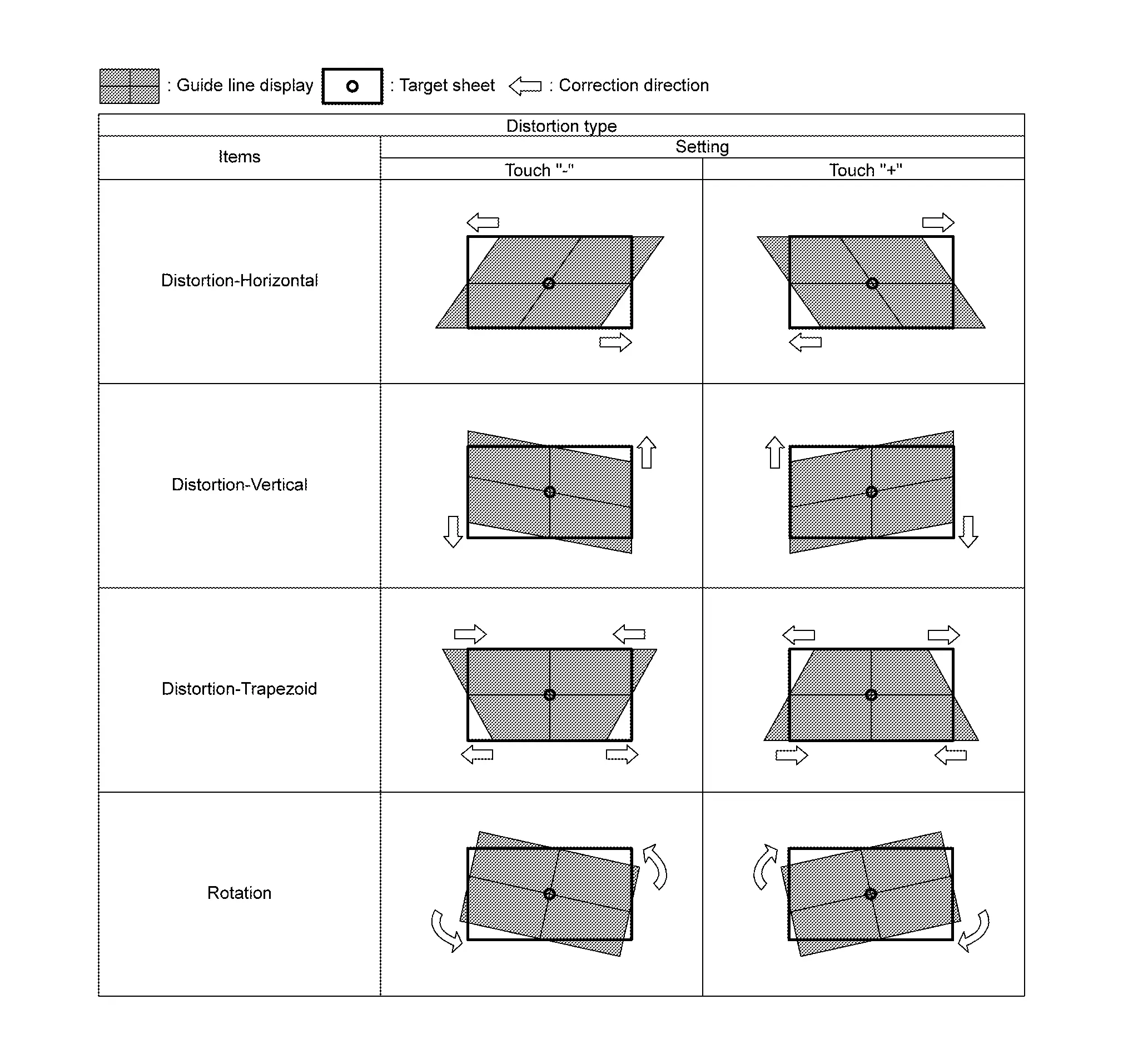
Touch "Save" and save the setting when calibration is completed.
NOTE:Touch "Reset" to cancel the change.
WORK END


Other materials:
Removal and Installation
REMOVAL
Remove front grille. Refer to Removal and Installation.
Disengage fixing pawl.
: Pawl
Disconnect harness connector to remove ambient sensor .
INSTALLATION
Install in the reverse order of removal. ...
Disassembly and Assembly
DISASSEMBLY
Disengage the pawl and turn EVAP canister vent control valve counterclockwise.
: Lock : Unlock
Remove the EVAP canister vent control valve.
ASSEMBLY
Assemble in the reverse order of disassembly.
CAUTION:
Do not reuse O-rings. ...
Hydraulic Layout
EVAP canister purge volume control solenoid valve EVAP resonator EVAP line Fuel line Fuel tank Fuel filler neck EVAP canister ...

0.0051