Ldw
Work Procedure
-
Perform action test to verify the customer's concern.
-
Perform action test and check the system operation after system diagnosis.
WARNING:
Be careful of traffic conditions and safety around the vehicle when performing road test.
CAUTION:
-
Fully understand the following items well before the road test;
-
System description: System Description
-
Handling precaution: Handling Precaution
-
CHECK LDW SYSTEM SETTING
-
Start the engine, and then wait for 30 seconds or more.
-
Check that the LDW system setting can be enabled/disabled on the information display.
-
Turn OFF the ignition switch and wait for 5 seconds or more.
-
Check that the previous setting is saved when the engine starts again.
>>
GO TO 2.
ACTION TEST FOR LDW
-
Turn LDW system ON.
-
Check the LDW operation according to the following table.
Condition Action Display on information display Buzzer LDW OFF — 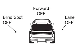
OFF LDW ON vehicle speed is less than approx. 60 km/h (37 MPH) — LDW system indicator : White
Speaker icon : White
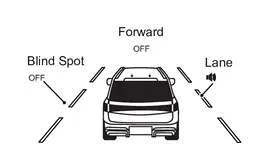
OFF vehicle speed is approx. 60 km/h (37 MPH) or more Vehicle closes to lane marker Turn signal is OFF or ON (Opposite to the deviate side) — Yellow (Blink)
Beep LDW system indicator : Yellow (Blink)
Speaker icon : White
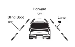
Turn signal is ON(Deviate side) — LDW system indicator : White
Speaker icon : White
OFF  NOTE:
NOTE:
After the operating conditions of warning are satisfied, the warning continues until the vehicle speed reaches approximately 55 km/h (34 MPH). Refer to System Description.
>>
INSPECTION END
I-Li
Work Procedure
-
Perform action test to verify the customer's concern.
-
Perform action test and check the system operation after system diagnosis.
WARNING:
Be careful of traffic conditions and safety around the vehicle when performing road test.
CAUTION:
-
Fully understand the following items well before the road test;
-
System description: Refer to System Description.
-
Handling precaution: Refer to Precautions for Intelligent Lane Intervention.
-
CHECK I-LI SYSTEM SETTING
-
Start the engine, and then wait for 30 seconds or more.
-
Check that the I-LI system setting can be enabled/disabled on the information display.
-
Turn OFF the ignition switch and wait for 5 seconds or more.
-
Check that the previous setting is saved when the engine starts again.
>>
GO TO 2.
ACTION TEST FOR I-LI
-
Turn I-LI system display ON.
-
Check the I-LI operation according to the following table.
Condition Action Display on information display Buzzer I-LI OFF — OFF I-LI ON vehicle speed is less than approx. 60 km/h (37 MPH) — I-LI system indicator: White
Speaker icon : White
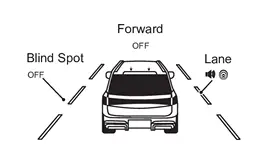
OFF vehicle speed is approx. 60 km/h (37 MPH) or more Vehicle closes to lane marker Turn signal is OFF or ON (Opposite to the deviate side) Yawing control is ON Yellow (Blink)
OFF I-LI system indicator: Yellow (Blink)
Speaker icon : White
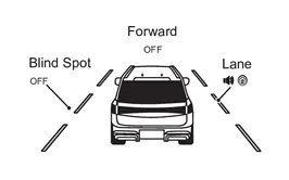
Turn signal is ON (Deviate side) — I-LI system indicator: White
Speaker icon : White
OFF vehicle closes to lane marker with soft braking — Yawing control is ON Yellow (Blink)
OFF I-LI system indicator: Yellow (Blink)
Speaker icon : White
NOTE:
After the operating conditions of warning are satisfied, the warning continues until the vehicle speed reaches approximately 60 km/h (37 MPH). Refer to System Description.
>>
INSPECTION END
Bsw
Work Procedure
-
Perform action test to verify the customer's concern.
-
Perform action test and check the system operation after system diagnosis.
CAUTION:
Fully understand the following items well before the road test;
-
System description: System Description
-
Handling precaution: Handling Precaution
CHECK BSW SYSTEM SETTING
-
Start the engine, and then wait for 30 seconds or more.
-
Check that the BSW system setting can be enabled/disabled on the information display.
-
Turn OFF the ignition switch and wait for 5 seconds or more.
-
Check that the previous setting is saved when the engine starts again.
>>
GO TO 2.
BSW SYSTEM ACTION TEST
-
Turn BSW system ON.
-
Check BSW operation according to the following table.
Condition Action Indication on the BSW indicator Display on information display Buzzer BSW OFF — OFF OFF BSW ON vehicle speed is less than approx. 32 km/h (20 MPH) — OFF BSW system indicator : White
Speaker icon : White
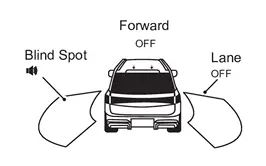
OFF vehicle speed is approx. 32 km/h (20 MPH) or more Vehicle is not detected — OFF BSW system indicator : White
Speaker icon : White
OFF vehicle is detected Turn signal is OFF — ON BSW system indicator : White
Speaker icon : White
OFF vehicle is detected before turn signal operates Turn signal is ON (vehicle detected direction) — Blink Yellow (Blink)
Short continuous beeps BSW system indicator : Yellow (Blink)
Speaker icon : White
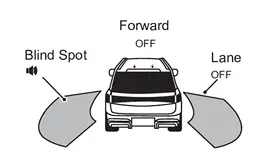
vehicle is detected after turn signal operates Turn signal is ON (vehicle detected direction) — Blink Yellow (Blink)
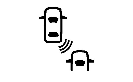
OFF BSW system indicator : Yellow (Blink)
Speaker icon : White
NOTE:
If vehicle speed exceeds approximately 32 km/h (20 MPH), BSW function operates until the vehicle speed becomes lower than approximately 29 km/h (18 MPH).
>>
INSPECTION END
I-Bsi
Work Procedure
-
Perform action test to verify the customer's concern.
-
Perform action test and check the system operation after system diagnosis.
NOTE:
Perform the Intelligent Blind Spot Intervention system action test after checking that the I-LI system operates normally because the Intelligent Blind Spot Intervention system shares components with the I-LI system.
WARNING:
Be careful of traffic conditions and safety around the vehicle when performing road test.
CAUTION:
Fully understand the following items well before the road test;
-
System description: Refer to System Description.
-
Handling precaution: Refer to Precautions for Intelligent Blind Spot Intervention.
LDW/I-LI SYSTEM ACTION TEST
Perform the LDW/I-LI system action test.
-
LDW: Refer to System Description.
-
I-LI: Refer to System Description.
>>
GO TO 2.
CHECK I-BSI SYSTEM SETTING
-
Start the engine.
-
Check that the I-BSI system setting can be enabled/disabled on the information display.
-
Turn OFF the ignition switch and wait for 5 seconds or more.
-
Check that the previous setting is saved when the engine starts again.
>>
INSPECTION END
Tsr
Work Procedure
-
Perform action test to verify the customer's concern.
-
Perform action test and check the system operation after system diagnosis.
WARNING:
Be careful of traffic conditions and safety around the vehicle when performing road test.
CAUTION:
-
Fully understand the following items well before the road test;
-
System description for TSR: Refer to System Description.
-
Handling precaution: Refer to Precautions for Traffic Sign Recognition.
-
CHECK TSR SYSTEM SETTING
-
Start the engine.
-
Start the engine, and then wait for 30 seconds or more.
-
Enable the setting of the TSR system on the information display.
-
Turn OFF the ignition switch and wait for 5 seconds or more.
-
Check that the previous setting is saved when the engine starts again.
>>
GO TO 2.
ACTION TEST FOR TSR
-
Enable the setting of the TSR system on the information display.
-
Check the TSR operation according to the following table.
System status Condition Display on information display Display on Head Up Display TSR OFF — — — TSR ON Road sign not detected — — Road sign detected (except for speed limit signs) This is an example. For details of displayed signs, Refer to System Description.
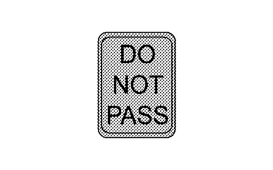
This is an example. For details of displayed signs, Refer to System Description.
Road sign detected (Speed limit signs) This is an example. For details of displayed signs, Refer to System Description.
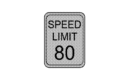
This is an example. For details of displayed signs, Refer to System Description.
TSR is malfunction The TSR system is automatically canceled. Malfunction
See Owner’s Manual—
>>
INSPECTION END
Rcta
Work Procedure
-
Perform action test to verify the customer's concern.
-
Perform action test and check the system operation after system diagnosis.
WARNING:
Be careful of traffic conditions and safety around the vehicle when performing road test.
CAUTION:
-
Fully understand the following items well before the road test;
-
System description for RCTA: Refer to System Description.
-
Handling precaution: Refer to Precautions for Rear Cross Traffic Alert.
-
CHECK RCTA SYSTEM SETTING
-
Start the engine, and then wait for 30 seconds or more.
-
Enable the setting of the RCTA system on the information display.
-
Turn OFF the ignition switch and wait for 5 seconds or more.
-
Check that the previous setting is saved when the engine starts again.
>>
GO TO 2.
ACTION TEST FOR RCTA
-
Enable the setting of the RCTA system on the information display.
-
Check the RCTA operation according to the following table.
Condition Action Indication on the BSW indicator Display on information display Buzzer RCTA OFF — OFF — OFF RCTA ON Shift position is in any position other than reverse — OFF — OFF Shift position is in reverse vehicle speed is less then approx. 8 km/h (5 MPH) Vehicle is not detected — OFF — OFF vehicle is detected — Blink — ON vehicle speed is approx. 8 km/h (5 MPH) or more Vehicle is detected — OFF — OFF
>>
INSPECTION END
I-Da
Work Procedure
-
Perform action test to verify the customer's concern.
-
Perform action test and check the system operation after system diagnosis.
WARNING:
Be careful of traffic conditions and safety around the vehicle when performing road test.
CAUTION:
-
Fully understand the following items well before the road test;
-
System description for I-DA: Refer to System Description.
-
Handling precaution: Refer to Precautions for Intelligent Driver Alertness.
-
CHECK I-DA SYSTEM SETTING
-
Start the engine, and then wait for 30 seconds or more.
-
Check that the I-DA system setting can be enabled/disabled on the information display.
-
Turn OFF the ignition switch and wait for 5 seconds or more.
-
Check that the previous setting is saved when the engine starts again.
>>
GO TO 2.
ACTION TEST FOR I-DA
-
Enable the setting of the I-DA system on the information display.
-
Check the I-DA operation according to the following table.
vehicle condition/ Driver’s operation Display on combination meter Buzzer I-DA OFF — OFF I-DA ON 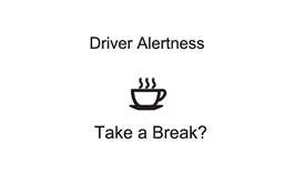
ON
>>
INSPECTION END
Other materials
Evap Canister
Exploded View
Vent hose 1
Canister filter
Bracket 3
EVAP canister
Vent hose 2
Bracket 1
Vent hose 3
EVAP canister vent control valve
Clip
EVAP control system pressure sensor
Bracket 2
Vent hose 4
Clamp
To fuel tank. Refer to F ...
Door Does Not Lock/unlock and Engine Does Not Start (one I-Key/req Sw/push Sw)
Description
All doors do not lock/unlock using one touch sensor and engine does not start when push-button ignition switch is pressed while carrying Intelligent Key. (One Intelligent Key has the symptom, other keys operate normally.)SYMPTOM TABLE (ONE INTELLIGENT KEY HAS THE SYMPTOM, OTHER KEYS OPER ...
Additional Service When Replacing Head up Display Unit
Work Procedure
DescriptionWhen replacing or removing the Head Up Display unit, distortion calibration of the display and adjustment of the display position are required.Work ProcedureREPLACE HEAD UP DISPLAY UNIT
Replace Head Up Display unit. Refer to Removal and Installation.
>>
GO TO 2.
PER ...