
Nissan Armada 2025-2026 Service and Repair Manual: Adjustment
WARNING:
Inspection
Perform inspection as follows after removal, installation or replacement of camshaft or valve-related parts, or if there is unusual engine conditions regarding valve clearance.
In cases of removing/installing or replacing camshaft and valve-related parts, or of unusual engine conditions due to changes in valve clearance (found malfunctions during stating, idling or causing noise), perform inspection as follows:
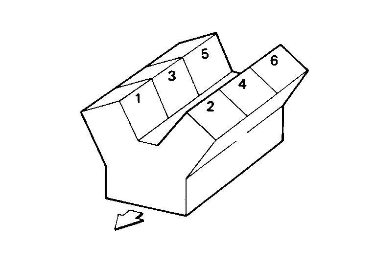
 | : Engine front |
Remove rocker covers (bank 1 and bank 2).
Measure the valve clearance as follows:
Set No. 1 cylinder at TDC of its compression stroke.
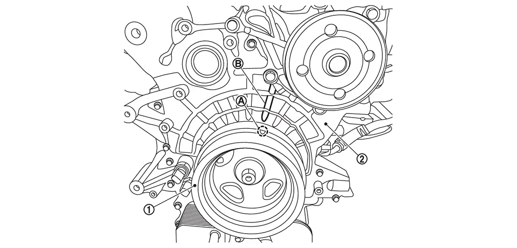
Rotate the crankshaft pulley clockwise as viewed from the front of the engine, and align the timing mark (grooved line without color)
 on the crankshaft pulley
  with
with  (fourth from the end on the bank 2 side) on the front cover
  .
.
Check that intake and exhaust cam nose on No. 1 cylinder (engine front side of bank 1) are located as shown in the figure.
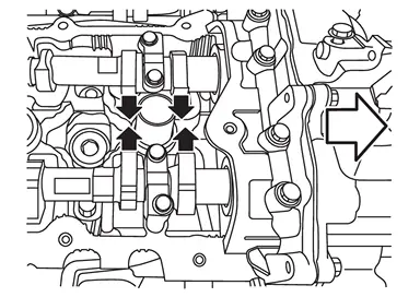
: Engine front If not, turn crankshaft one revolution (360 degrees) and align as shown in the figure.
Use a feeler gauge (commercial service tool), measure the clearance between valve lifter and camshaft.
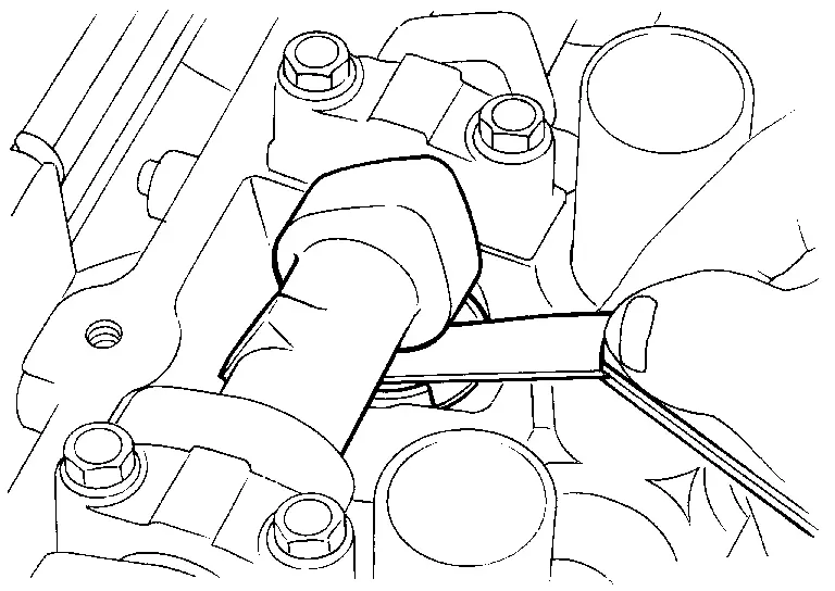
Valve clearance : Refer to Camshaft By referring to the figure, measure the valve clearances at locations marked “×� as shown in the table below (locations indicated in the figure).
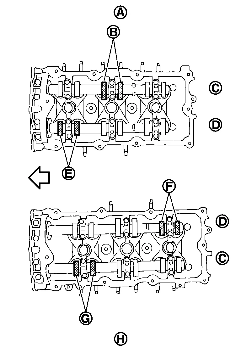
: Engine front No. 1 cylinder at compression TDC
Measuring position [bank 1 ] No. 1 CYL. No. 3 CYL. No. 5 CYL. No. 1 cylinder at compression TDC EXH 
× INT 
× 
Measuring position [bank 2  ]
] No. 2 CYL. No. 4 CYL. No. 6 CYL. No. 1 cylinder at compression TDC INT × 
EXH × 
Rotate crankshaft 240 degrees clockwise (when viewed from engine front) to align No. 3 cylinder at TDC its compression stroke.
 NOTE:
NOTE:Mark a position 240 degrees
 from a corner of the hexagonal part of crankshaft pulley mounting bolt as shown in the figure. Use the hexagonal part as a guide.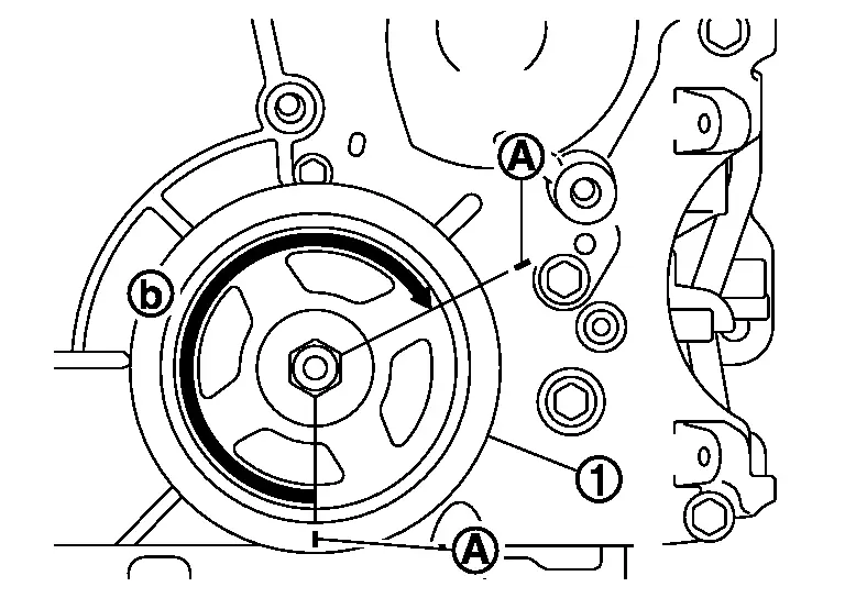
: Crankshaft pulley : Paint mark 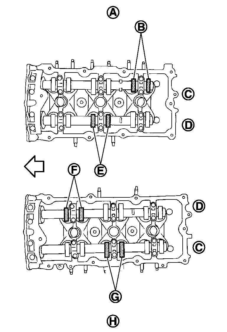
: Engine front No. 3 cylinder at compression TDC
Measuring position [bank 1 ] No. 1 CYL. No. 3 CYL. No. 5 CYL. No. 3 cylinder at compression TDC EXH × INT × Measuring position [bank 2 ] No. 2 CYL. No. 4 CYL. No. 6 CYL. No. 3 cylinder at compression TDC INT × EXH ×
Rotate crankshaft 240 degrees clockwise (when viewed from engine front) to align No. 5 cylinder at TDC of compression stroke.
NOTE:Mark a position 240 degrees
from a corner of the hexagonal part of crankshaft pulley mounting bolt as shown in the figure. Use the hexagonal part as a guide.: Crankshaft pulley : Paint mark 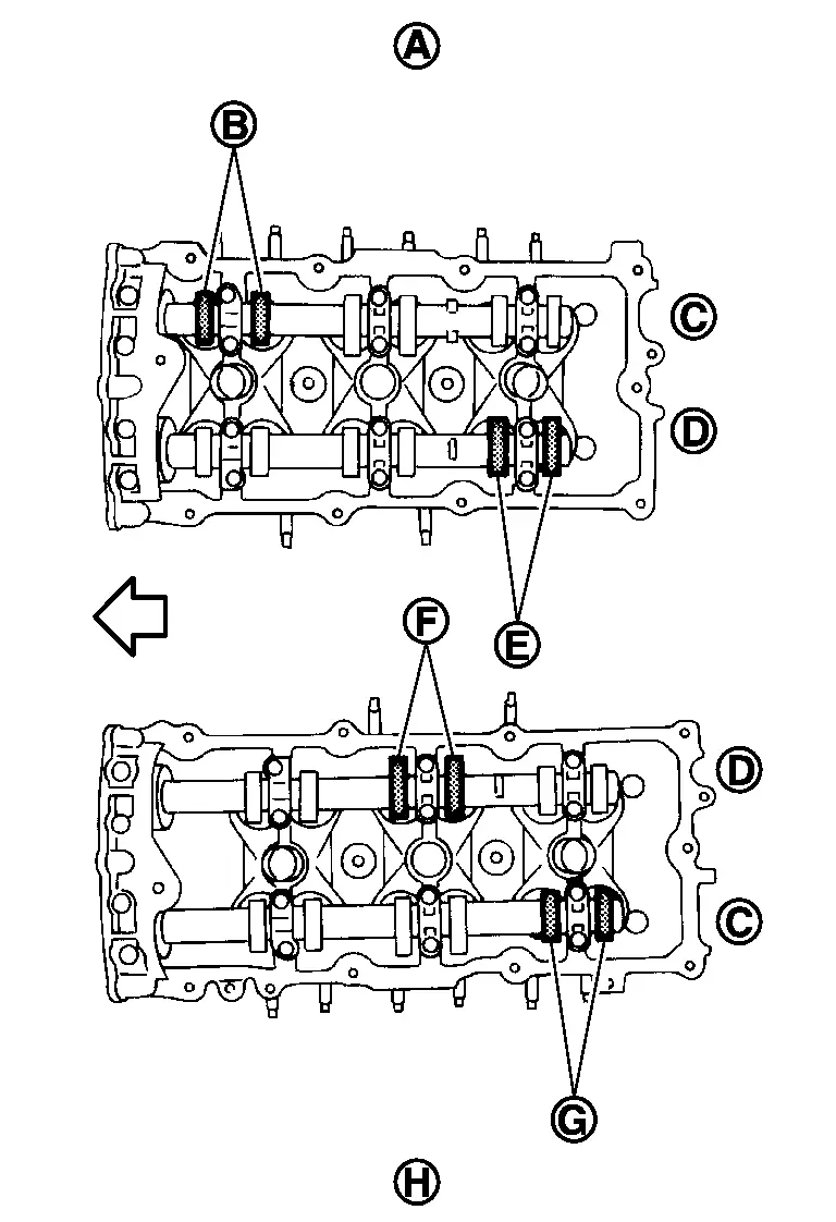
: Engine front No. 5 cylinder at compression TDC
Measuring position [bank 1 ] No. 1 CYL. No. 3 CYL. No. 5 CYL. No. 5 cylinder at compression TDC EXH × INT × Measuring position [bank 2 ] No. 2 CYL. No. 4 CYL. No. 6 CYL. No. 5 cylinder at compression TDC INT × EXH ×
Perform adjustment if the measured value is out of the standard. Refer to “ADJUSTMENT�.
ADJUSTMENT
Perform adjustment depending on selected head thickness of valve lifter.
Measure the valve clearance. Refer to “INSPECTION�.
Remove camshaft.
Remove valve lifters at the locations that are out of the standard.
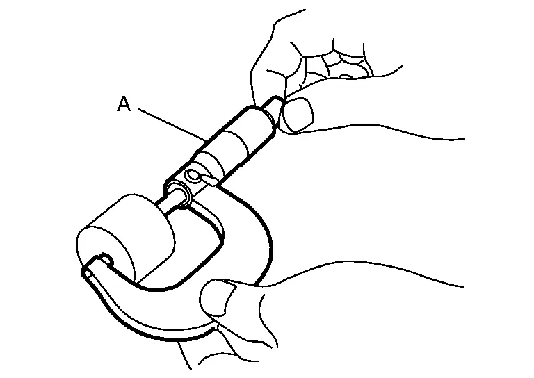
Measure the center thickness of the removed valve lifters with a micrometer (A).
Use the equation below to calculate valve lifter thickness for replacement.
Valve lifter thickness calculation: t = t1+ (C1 – C2) t = Valve lifter thickness to be replaced t1 = Removed valve lifter thickness C1 = Measured valve clearance C2 = Standard valve clearance: Intake : 0.30 mm (0.0118 in) Exhaust : 0.32 mm (0.0126 in) Thickness of new valve lifter can be identified by stamp marks on the reverse side (inside the cylinder).
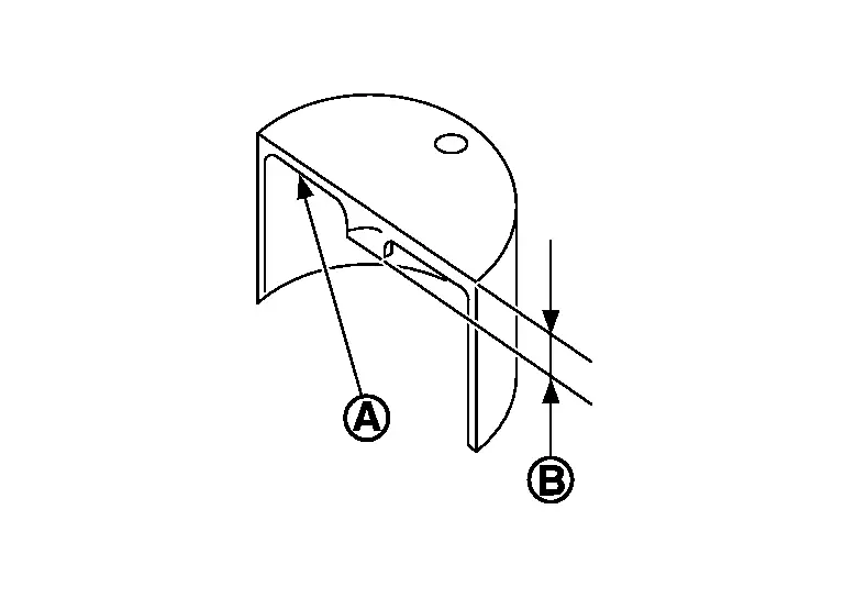
Thickness of new valve lifter can be identified by stamp marks on the reverse side (inside the cylinder).
Stamp mark 300 indicates 3.00 mm (0.1181 in) in thickness.
: Stamp : Thickness of valve lifter Available thickness of valve lifter: 26 sizes with range 3.00 to 3.50 mm (0.1181 to 0.1378 in) in steps of 0.02 mm (0.0008 in) (when manufactured at factory).
Install selected valve lifter.
Install camshaft.
Manually turn crankshaft pulley a few turns.
Check that the valve clearances for cold engine are within the specifications by referring to the specified values. Refer to “INSPECTION�.
Install all removal parts in the reverse order of removal.
Warm up the engine, and check for unusual noise and vibration.
 Inspection
INSPECTION AFTER REMOVAL
Camshaft Runout
Put V-block on precise flat table, and support No. 2 and 4 journals of camshaft.
CAUTION:
Never support No. 1 journal (on the side of camshaft sprocket) beca ...
 Cylinder Head
...
Other materials:
Inspection Procedure
INSTRUMENT PANEL
Most incidents are caused by contact and movement between:
Cluster lid A and instrument panel
Acrylic lens and combination meter housing
Instrument panel to front pillar garnish
Instrument panel to windshield
Instrument panel mounting pins
Wiring harnesses behind the combination met ...
Special Service Tools
The actual shape of the tools may differ from those illustrated here.Tool number
(TechMate No.)
Tool name Description  — 
(NI-44372)
Pull gauge
Measuring steering wheel turning force and ball joint swinging force KV40107300
(NI-51751)
Boot band crimping tool
Installing boot clamp (large ...
Precautions on supplemental restraint system
This section describes the Supplemental Restraint System (SRS) in the Nissan
Armada and provides essential safety information regarding its operation. The Nissan
Armada is equipped with multiple advanced protection systems designed to work together
with seat belts to reduce the risk of injury ...

0.0057