
Nissan Armada 2025-2026 Service and Repair Manual: Inspection
INSPECTION AFTER REMOVAL
Camshaft Runout
Put V-block on precise flat table, and support No. 2 and 4 journals of camshaft.
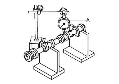
CAUTION:
Never support No. 1 journal (on the side of camshaft sprocket) because it has a different diameter from the other three locations.
| A | : Dial indicator | |
Set a dial indicator vertically to No. 3 journal.
Turn camshaft to one direction with hands, and measure the camshaft runout on a dial indicator. (Total indicator reading)
| Standard and limit | : Refer to Camshaft. |
If it exceeds the limit, replace camshaft.
Camshaft Cam Height
Measure the camshaft cam height with a micrometer (A).
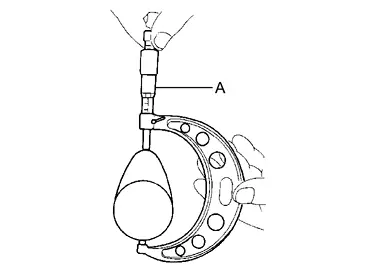
| Standard cam height | : Refer to Camshaft. |
| (Intake and exhaust) | |
| Cam wear limit |
If wear exceeds the limit, replace camshaft.
Camshaft Journal Oil Clearance
CAMSHAFT JOURNAL DIAMETER
Measure the outer diameter of camshaft journal with a micrometer (A).
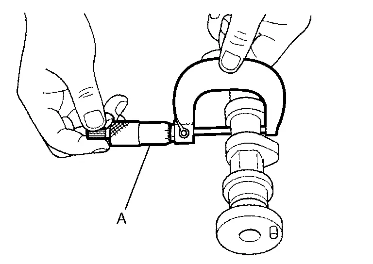
Standard : Refer to Camshaft.
CAMSHAFT BRACKET INNER DIAMETER
Tighten camshaft bracket bolt with the specified torque. Refer to “INSTALLATION� for the tightening procedure.
Measure inner diameter (A) of camshaft bracket with a bore gauge.
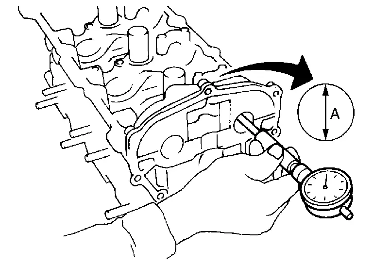
Standard : Refer to Camshaft.
CAMSHAFT JOURNAL OIL CLEARANCE
(Oil clearance) = (Camshaft bracket inner diameter) – (Camshaft journal diameter).
Standard and limit : Refer to Camshaft. If the calculated value exceeds the limit, replace either or both camshaft and cylinder head.
 NOTE:
NOTE:Camshaft brackets cannot be replaced as single parts, because there are machined together with cylinder head. Replace whole cylinder head assembly.
Camshaft End Play
Install a dial indicator in thrust direction on front end of camshaft. Measure the end play of a dial indicator when camshaft is moved forward/backward (in direction to axis).
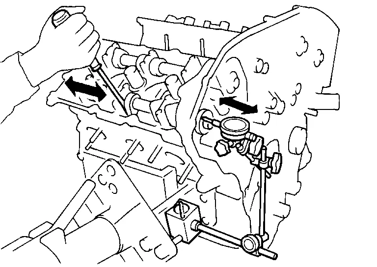
Standard and limit : Refer to Camshaft. Measure the following parts if out of the limit.
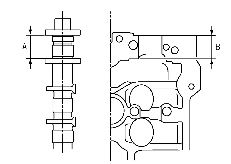
Dimension “A� for camshaft No. 1 journal
Standard : 27.500 - 27.548 mm (1.0827 - 1.0846 in) Dimension “B� for cylinder head No. 1 journal bearing
Standard : 27.360 - 27.385 mm (1.0772 - 1.0781 in)
Refer to the standards above, and then replace camshaft and/or cylinder head.
Camshaft Sprocket Runout
Put V-block on precise flat table, and support No. 2 and 4 journals of camshaft.
CAUTION:
Never support No. 1 journal (on the side of camshaft sprocket) because it has a different diameter from the other three locations.
Measure the camshaft sprocket runout with a dial indicator. (Total indicator reading)
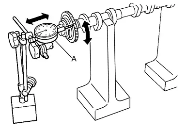
| Limit | : Refer to Camshaft. |
If it exceeds the limit, replace camshaft sprocket.
A : Dial indicator
Valve Lifter
Check if surface of valve lifter has any wear or cracks.
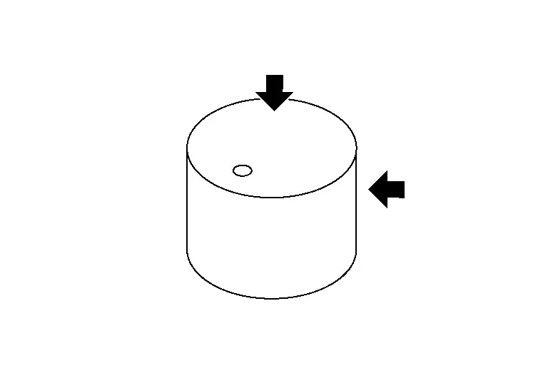
If anything above is found, replace valve lifter. Refer to Camshaft.
Valve Lifter Clearance
VALVE LIFTER OUTER DIAMETER
Measure the outer diameter at 1/2 height of valve lifter with a micrometer (A) since valve lifter is in barrel shape.
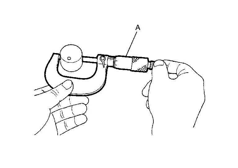
Standard : Refer to Camshaft. (Intake and exhaust)
VALVE LIFTER HOLE DIAMETER
Measure the inner diameter of valve lifter hole of cylinder head with an inside micrometer (A).
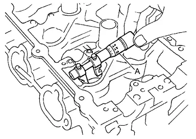
Standard : Refer to Camshaft. (Intake and exhaust)
VALVE LIFTER CLEARANCE
(Valve lifter clearance) = (Valve lifter hole diameter) – (Valve lifter outer diameter)
Standard : Refer to Camshaft. (Intake and exhaust) If the calculated value is out of the standard, referring to each standard of valve lifter outer diameter and valve lifter hole diameter, replace either or both valve lifter and cylinder head.
INSPECTION AFTER INSTALLATION
Inspection of Camshaft Sprocket (EXH) Oil Groove
CAUTION:
Perform this inspection only when DTC P0014, P0024 is detected in self-diagnostic results of CONSULT and it is directed according to inspection procedure of EC section. Refer to DTC Description.
Check when engine is cold so as to prevent burns from the splashing engine oil.
Check engine oil level. Refer to Inspection.
Turn ignition switch to “START� for cranking.
 With CONSULT
Remove exhaust valve timing control solenoid valve. Refer to Exploded View.
 Without CONSULT
Release the fuel pressure. Refer to Work Procedure.
Disconnect fuel pump fuse from IPDM E/R to avoid fuel injection during measurement. Refer to Wiring Diagram.
Remove exhaust valve timing control solenoid valve. Refer to Exploded View.
Crank engine, and then check that engine oil comes out from exhaust valve timing control solenoid valve hole  . End crank after checking.
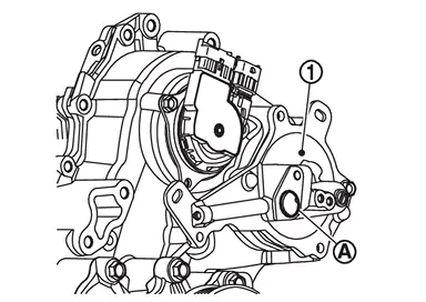
 | : Valve timing control cover (bank 1) |
WARNING:
Never touch rotating parts. (crankshaft pulley, etc.)
CAUTION:
Prevent splashing by using a shop cloth so as to prevent the worker from injury from engine oil and so as to prevent engine oil contamination.
Use waste to protect the engine and vehicle from the splattering of engine oil. Special care must be taken on the protection of rubber parts, such as engine mount insulator. If engine oil splatters to the rubber parts, immediately wipe it out.
Perform the following inspection if engine oil does not come out from exhaust valve timing control solenoid valve oil hole of the cylinder head.
Clean oil groove between oil strainer and exhaust valve timing control solenoid valve. Refer to Engine Lubrication System.
Remove components between exhaust valve timing control solenoid valve and camshaft sprocket, and then check each oil groove for clogging.
Clean oil groove if necessary. Refer to Engine Lubrication System.
After inspection, install removed parts in the reverse order.
Inspection for Leakage
The following are procedures for checking fluids leakage, lubricates leakage.
Before starting engine, check oil/fluid levels including engine coolant and engine oil. If less than required quantity, fill to the specified level. Refer to Fluids and Lubricants.
Use procedure below to check for fuel leakage.
Turn ignition switch “ON� (with engine stopped). With fuel pressure applied to fuel piping, check for fuel leakage at connection points.
Run engine to check for unusual noise and vibration.
NOTE:If hydraulic pressure inside timing chain tensioner drops after removal/installation, slack in the guide may generate a pounding noise during and just after engine start. However, this is normal. Noise will stop after hydraulic pressure rises.
Warm up engine thoroughly to check there is no leakage of fuel, or any oil/fluids including engine oil and engine coolant.
Bleed air from lines and hoses of applicable lines, such as in cooling system.
Summary of the inspection items: Items Before starting engine Engine running After engine stopped Engine coolant Level Leakage Level Engine oil Level Leakage Level Transmission / transaxle fluid AT & CVT Models Leakage Level / Leakage Leakage MT Models Level / Leakage Leakage Level / Leakage Other oils and fluids* Level Leakage Level Fuel Leakage Leakage Leakage Exhaust gases — Leakage — *: Power steering fluid, brake fluid, etc.
 Removal & Installation
WARNING:
REMOVAL
Remove front cover. Refer to Removal & Installation.
Remove timing chain. Refer to Removal and Installation.
Remove fuel tube assembly. Refer to Removal and Installation.
Remove h ...
 Adjustment
WARNING:
Inspection
Perform inspection as follows after removal, installation or replacement of camshaft or valve-related parts, or if there is unusual engine conditions regarding valve clearance.
In ...
Other materials:
Normal Operating Condition
Because of modified sine wave output, the AC 120V outlet may not operate normally for electric appliance of which electric power consumption is 150W or less.
Electric appliances requiring a large amount of electric power consumption at startup (e.g., CRT-based TV, power tool)
Measuring instruments f ...
Removal and Installation
CAUTION:
Never damage the back door panel.
REMOVAL
CAUTION:
Fully open back door.
Apply protective tape (A) on back door lower finisher to protect it from damage.
Disengage automatic back door switch finisher fixing pawls using a remover tool (A).
: Pawl
Disconnect harness connectors, and the ...
Steering Assist with HD map data (a feature of ProPILOT Assist 2.1)
In the Nissan Armada equipped with ProPILOT Assist 2.1, Steering Assist is enhanced
by HD map data, enabling more advanced driving support. When all required conditions
are met, the system indicator turns blue, signaling that enhanced functionality
is active.
In this advanced mode, the Nissan ...

0.0056