Exploded View
REMOVAL
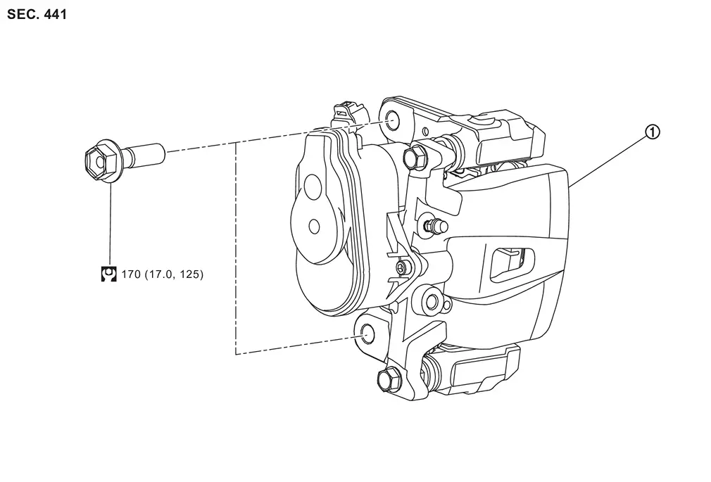
 |
Brake caliper assembly | ||||
 |
: N·m (kg-m, ft-lb) |
DISASSEMBLY
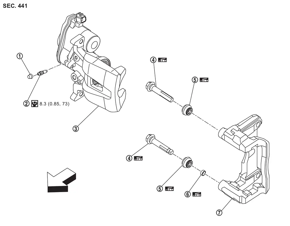
|
Cap |  |
Bleeder valve |  |
Cylinder body |
 |
Sliding pin |  |
Sliding pin boot |  |
Bushing |
 |
Torque member | ||||
| : vehicle front | |||||
 |
: N·m (kg-m, in-lb) | ||||
 |
: Apply rubber grease. | ||||
Removal and Installation
WARNING:
-
Jacking up or lift up the vehicle may the vehicle height to go down which cause a personal injury and/or damage to the air suspension component parts. Refer to Precaution for when Jacking and Lifting Up the vehicle with Electronic Air Suspension System.
REMOVAL
WARNING:
Since dust covering the front and rear brakes has an affect on human body, the dust must be removed with a dust collector. Never splatter the dust with an air blow gun.
CAUTION:
-
Never spill or splash brake fluid on painted surfaces. Brake fluid may seriously damage paint. Wipe it off immediately and wash with water if it gets on a painted surface.
-
Never depress the brake pedal while removing the brake pads because the piston may pop out.
-
If the brake fluid or grease adheres to the brake caliper assembly and disc rotor, quickly wipe it off.
Release the parking brake.
Remove tires. Refer to ROAD WHEEL TIRE : Removal & Installation.
Perform the advance preparation "(Air release) Accumulator pressure release" using CONSULT. Refer to Work Procedure.
Remove parking brake actuator harness and rear wheel sensor. Hang parking brake actuator harness and rear wheel sensor not to interfere with work. Refer to Removal and Installation.
Fix the disc rotor using wheel nuts.
Drain brake fluid. Refer to Draining.
Remove union bolt and copper washer, and separate brake hose from brake caliper assembly. Refer to Removal and Installation.
Remove sliding pin bolts  , and remove the cylinder body.
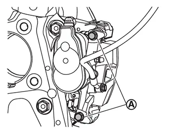
Remove torque member mounting bolts, and remove torque member.
CAUTION:
-
Never drop brake pad and brake caliper assembly.
-
Never damage the electric parking brake harness and bracket.
Remove disc rotor. Refer to Removal and Installation.
INSTALLATION
WARNING:
Since dust covering the front and rear brakes has an affect on human body, the dust must be removed with a dust collector. Never splatter the dust with an air blow gun.
CAUTION:
-
Never spill or splash brake fluid on painted surfaces. Brake fluid may seriously damage paint. Wipe it off immediately and wash with water if it gets on a painted surface.
-
Never depress the brake pedal while removing the brake pads because the piston may pop out.
-
If the brake fluid or grease adheres to the brake caliper assembly and disc rotor, quickly wipe it off.
-
Never allow foreign matter (e.g.dust) and oils other than brake fluid to enter the reservoir tank.
Install disc rotor. Refer to Removal and Installation.
Install the torque member to the steering knuckle and tighten the torque member mounting bolts to the specified torque. Refer to Exploded View.
CAUTION:
Never spill or splash any grease and moisture on the torque member mounting face, threads, mounting bolts and washers. Wipe out any grease and moisture.
Install the cylinder body to the torque member and tighten the sliding pin bolts to the specified torque. Refer to Exploded View.
CAUTION:
Never spill or splash any grease and moisture on the cylinder body mounting face, threads, mounting bolts and washers. Wipe out any grease and moisture.
Install brake hose and copper washers to brake caliper assembly. Refer to Removal and Installation.
CAUTION:
Never reuse copper washer.
Refill with new brake fluid and perform the air bleeding. Refer to Work Procedure.
CAUTION:
-
Never reuse brake fluid.
-
Never spill or splash brake fluid on the surface of disc rotor.
Must be performed additional service when replacing brake caliper assembly. Refer to Description.
Check a drag of rear disc brake. If any drag is found, refer to Inspection and Adjustment.
Install tires. Refer to ROAD WHEEL TIRE : Removal & Installation.
Perform inspection after installation. Refer to Inspection.
Disassembly and Assembly
DISASSEMBLY
 NOTE:
NOTE:
Never remove the torque member and brake pad when disassembling and assembling the cylinder body.
Remove the sliding pin bolt, and remove the cylinder body from the torque member. Refer to Removal and Installation.
CAUTION:
Fix the brake pad at suitable tape so that the brake pad will not drop.
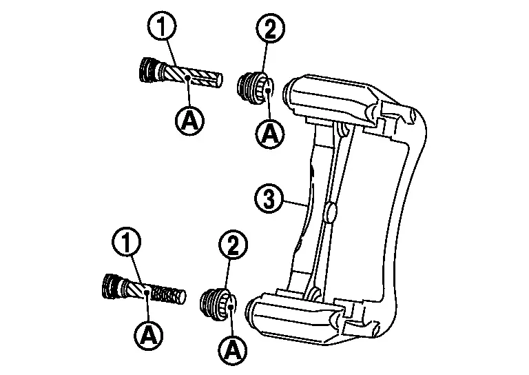
Remove sliding pins and sliding pin boots from torque member.
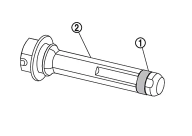
Remove bushing from sliding pin .
Remove bleeder valve and cap.
Perform inspection after disassembly. Refer to Inspection.
ASSEMBLY
Install bleeder valve and cap.
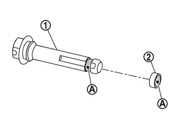
Apply rubber grease to mating faces between sliding pin and bushing , and install bushing to sliding pin.
Apply rubber grease to mating faces between sliding pins and sliding pin boots , and install sliding pins and sliding pin boots to torque member .
Install the cylinder body to tighten cylinder body mounting bolts to the specified torque. Refer to Exploded View.
Inspection
INSPECTION AFTER DISASSEMBLY
Check the following items and replace if necessary.
Cylinder Body
Check the cylinder inner wall for rust, wear, cracks or damage.
CAUTION:
Always clean with new brake fluid. Never clean with mineral oil such as gasoline and light oil.
Torque Member
Check the torque member for rust, wear, cracks or damage.
Sliding Pin, Sliding Pin Boot and Bushing
Check the sliding pins, sliding pin boots and bushing for rust, wear, cracks or damage.
INSPECTION AFTER INSTALLATION
-
Check a drag of rear disc brake. If any drag is found, follow the procedure described below.
-
Remove brake pads. Refer to Removal and Installation.
-
Press the pistons. Refer to Removal and Installation.
-
Install brake pads. Refer to Removal and Installation.
-
Depress the brake pedal several times.
-
Check a drag of rear disc brake again. When any drag is found, disassemble the cylinder body and replace if necessary. Refer to Disassembly and Assembly.
-
-
Burnish contact surfaces brake pads and disc rotor after refinishing or replacing disc rotor, or if a soft pedal occurs at very low mileage. Refer to Inspection and Adjustment.
Other materials
Rear Blower Motor
Exploded View
Rear A/C unit assembly
Rear blower motor
: vehicle front
Removal and Installation
REMOVALRemove rear A/C unit assembly. Refer to Removal and Installation.
Disconnect rear blower unit harness connector.
Remove fixing screws , and then remove rear blower motor. ...
Approach Unlock/walk Away Lock Function Does Not Operate (one Key)
Description
Approach unlock/walk away lock function does not operate. (One Intelligent Key has the symptom, other keys operate normally.)NOTE:
Before starting diagnosis check that vehicle condition is as shown in “Conditions of vehicle”, and check each symptom.SYMPTOM TABLE (BOTH INTELLIGENT KEY ...
Normal Operating Condition
Symptom Table
NOTE:
For Navigation system operation information, refer to Navigation system Owner's Manual.BASIC OPERATIONS Symptom Possible cause Possible solution
No image is displayed.
The brightness is at the lowest setting.
Adjust the brightness of the display.
The systems in the vid ...