Exploded View
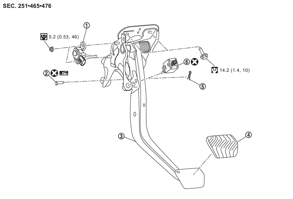
 |
Stroke sensor |  |
Clevis pin |  |
Brake pedal assembly |
 |
Brake pedal pad |  |
Snap pin |  |
Stop lamp switch |
 |
: N·m (kg-m, ft-lb) | ||||
 |
: N·m (kg-m, in-lb) | ||||
 |
: Apply Nissan multi-purpose Special Grease No.2 or equivalent. | ||||
 |
: Always replace after every disassembly. | ||||
Removal and Installation
REMOVAL
Remove driver knee air bag module. Refer to Removal and Installation.
Remove BCM. Refer to Removal and Installation.
Remove fuse block (J/B).
Disconnect the stop lamp switch harness connectors.
Remove stop lamp switch , follow the procedure below.
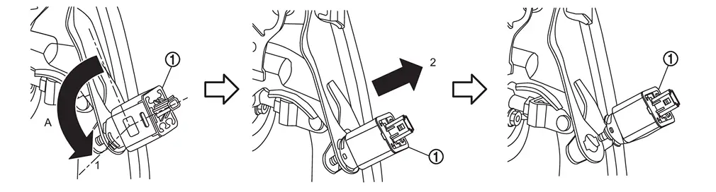
| A | : About 90 degree |
Disconnect the stroke sensor harness connector.
Remove stroke sensor if necessary.
Remove snap pin and clevis pin from clevis of electrical brake control unit .
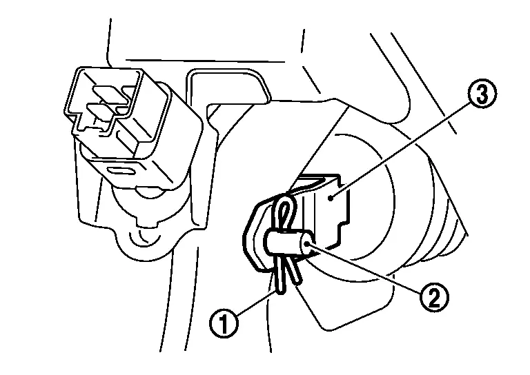
Remove harness clip from brake pedal.
Remove the electrical brake control unit mounting nuts from brake pedal assembly. Refer to Removal & Installation.
Remove the brake pedal assembly mounting bolts, and remove brake pedal assembly.
CAUTION:
Hold the electrical brake control unit so as not to drop out or contact them other parts.
Perform inspection after removal. Refer to Inspection.
INSTALLATION
Note the following, and install in the reverse order of removal.
-
Never reuse stop lamp switch.
-
Never reuse the clevis pin.
-
Apply the Nissan multi-purpose Special Grease No.2 or equivalent to the clevis pin and the mating faces.
 NOTE:
NOTE:
The clevis pin may be inserted in either direction.
-
Never impact brake pedal such as drop and interference with tools and parts.
-
Replace brake pedal when impacting brake pedal.
-
Install stop lamp switch
, follow the procedure below.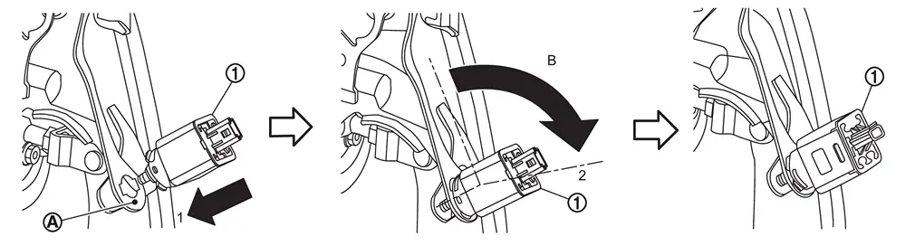
-
Penetrate the clip hole of stop lamp switch mounting bracket and firmly push the direction (1) the stop lamp switch against the stop lamp switch mounting bracket
 .
.B : About 90 degree -
Turn the stop lamp switch clockwise (2) until it stops.
-
-
Perform adjustment after installation. Refer to Adjustment.
-
Perform stroke sensor calibration when brake pedal assembly removed and installed, or replaced. Refer to Work Procedure.
-
Perform stroke sensor calibration when stroke sensor removed and installed, or replaced. Refer to Work Procedure.
Inspection
INSPECTION AFTER REMOVAL
Check the brake pedal assembly for bend, damage, and cracks on the welded parts. If any is found, replace brake pedal assembly.
Adjustment
ADJUSTMENT AFTER INSTALLATION
-
Adjust each item of brake pedal after installing the brake pedal assembly to the vehicle. Refer to Inspection and Adjustment.
-
Perform stroke sensor 0 point learning. Refer to Work Procedure.
Other materials
Tilt & Telescopic Switch
Removal and Installation
REMOVALRemove steering column cover lower. Refer to Removal and Installation.
Disengage the fixing pawls using a remover tool (A) and then remove tilt & telescopic switch.
: Pawl
INSTALLATIONInstall in the reverse order of removal. ...
Back Door Auto Closure Control Unit
Diagnosis Procedure
CHECK POWER SUPPLY AND GROUND CIRCUIT
Check back door auto closure control unit power supply and ground circuit.
Refer to XXX.
Is the inspection result normal?
YES>>
GO TO 2.
NO>>
Repair or replace the malfunctioning parts.
CHECK DTC WITH BACK DOOR AUTO CLOSURE CON ...
Charging System Tools and Preparation
Special Service Tools
Tool number
(TechMate No.)
Tool name Description
—
(—) Model GR8-1200 NI
Multitasking battery and electrical diagnostic station
Tests batteries, starting and charging systems and charges batteries.
For operating instructions, refer to diagnostic station instruction ...