
Nissan Armada 2025-2026 Service and Repair Manual: Connector Symbols
Most of connector symbols in wiring diagrams are shown from the terminal side.
Connector symbols shown from the terminal side are enclosed by a single line and followed by the direction mark.
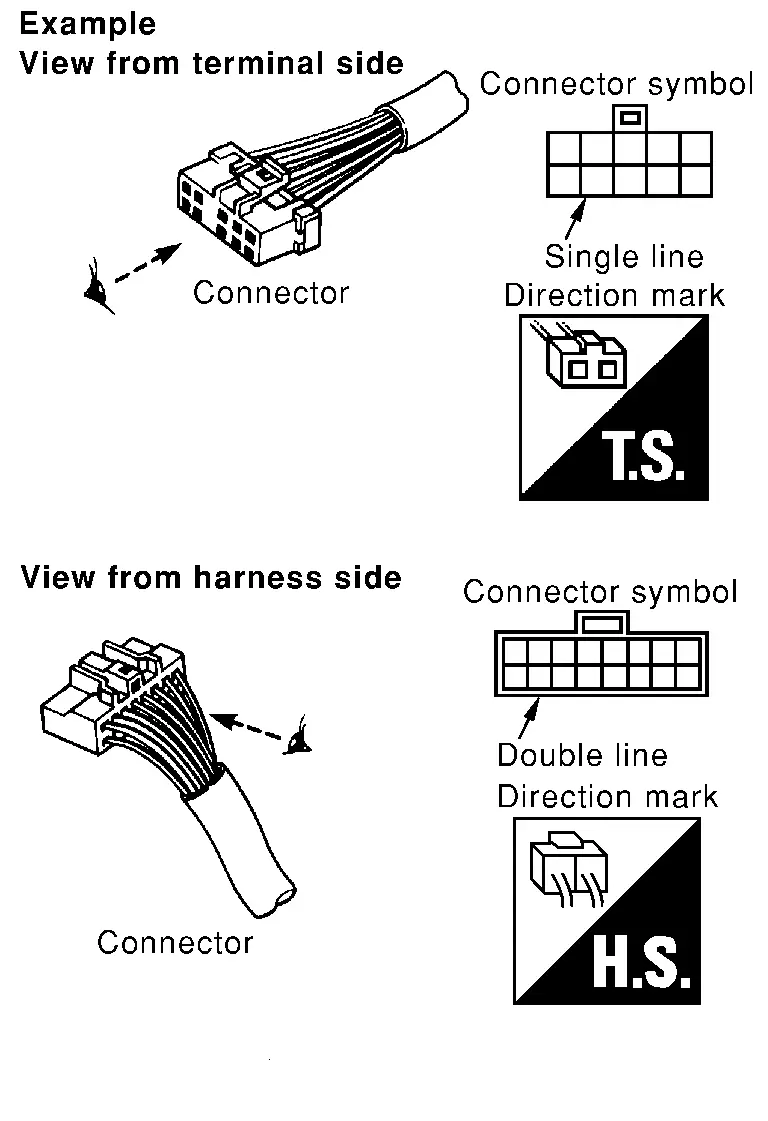
Connector symbols shown from the harness side are enclosed by a double line and followed by the direction mark.
Certain systems and components, especially those related to OBD, may use a new style slide-locking type harness connector. For description and how to disconnect, refer to PG section, “Description�, “HARNESS CONNECTOR�.
Male and female terminals
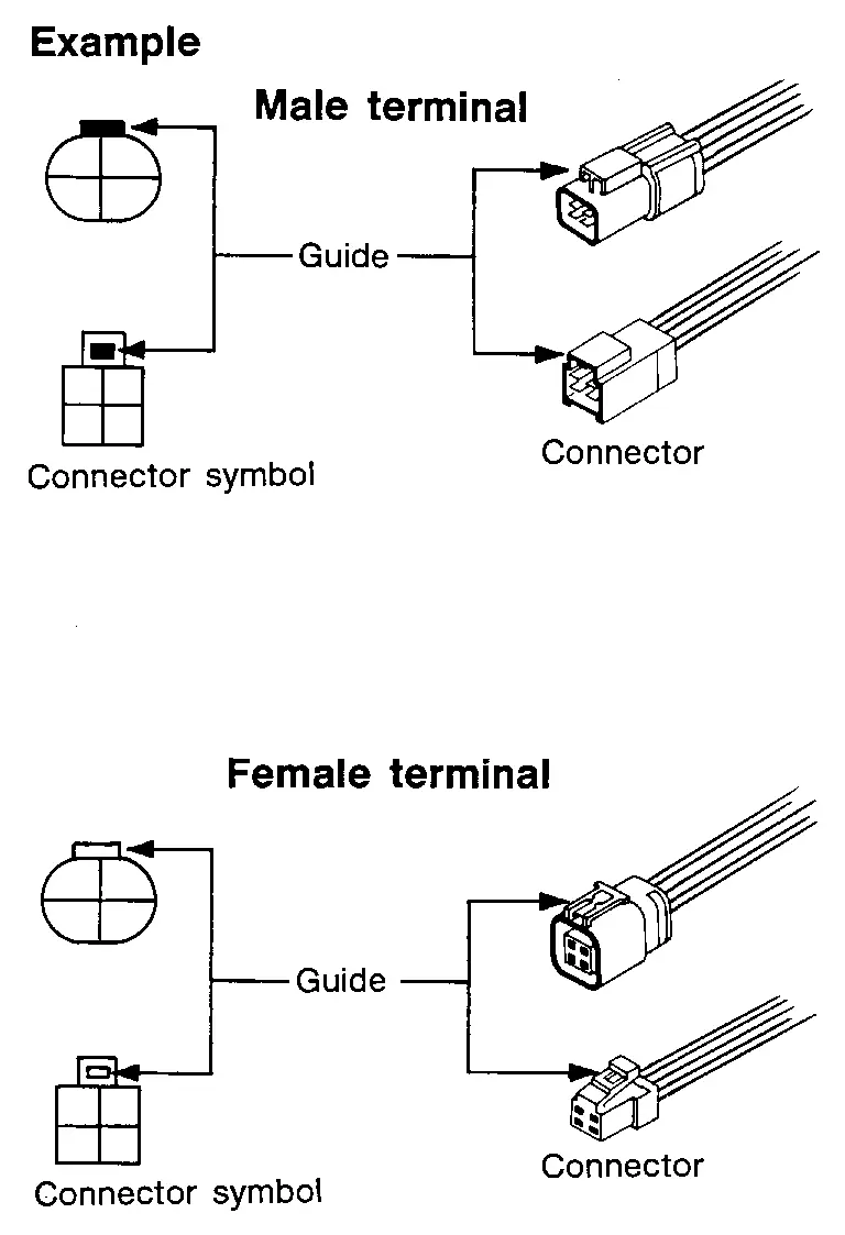
Connector guides for male terminals are shown in black and female terminals in white in wiring diagrams.
 Sample/Wiring Diagram -Example-
Each section includes wiring diagrams.
Description Number Item Description Power supply This means the power supply of fusible link or fuse.
Fuse “/� means the fuse.
Current rating of fusi ...
 How to Repair Aluminum Wires
PRECAUTIONS FOR THE HANDLING OF ALUMINUM WIRES
If an aluminum wire is damaged (e.g. broken), never perform the repair method for copper wires (soldering).
Never perform electrotap for connecting broke ...
Other materials:
Diagnosis Procedure
When ProPILOT Assist 1.1 system is active, the ProPILOT Assist 1.1 system does not perform any control even through there is a vehicle ahead.
CHECK ProPILOT ASSIST 1.1 SYSTEM DISPLAY ON INFORMATION DISPLAY
Start the self-diagnosis mode of combination meter. Refer to On Board Diagnosis Function.
Che ...
General Specification
Applied model Axle 2WD Engine VR35DDTT Transmission A/T Rear final drive R240 without differential lock Propeller shaft model 3F C-C-C Number of joints 3 Joint type 1st joint Universal (Solid type) 2nd joint Universal (Solid Type) 3rd joint Universal (Solid Type) Coupling method ...
Tire Pressure Monitoring System (TPMS)
Basic information
For optimal safety and performance of your Nissan Armada, each tire—including
the spare tire (if equipped)—should be inspected at least once a month when cold
and inflated according to the manufacturer’s recommended pressure values listed
on the vehicle placard or tire ...

0.0056