Work Flow
OVERALL SEQUENCE
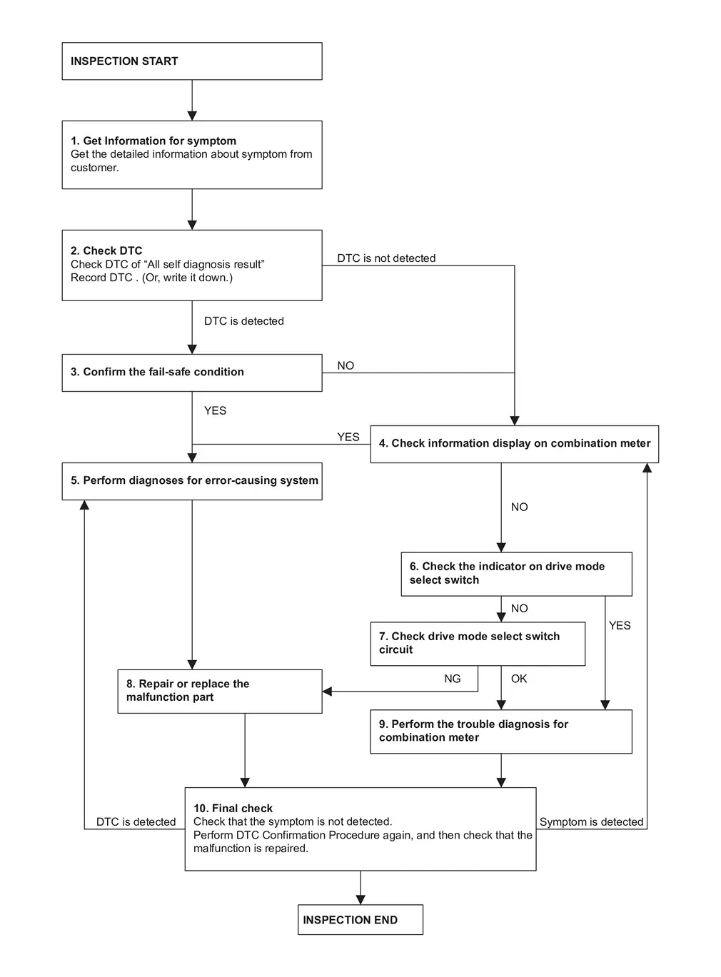
DETAILED FLOW
GET INFORMATION FOR SYMPTOM
-
Get the detailed information about symptom from customer.
-
Check the drive mode indicator on the meter appeared.
-
Check the drive mode indicator on the meter changed when operates the drive mode selector switch.
>>
GO TO 2.
CHECK THE DTC
 With CONSULT
-
Check DTC of “All self diagnosis result”.
-
Perform the following procedure if DTC is displayed.
-
Record DTC and freeze frame data. (Or, write it down.)
-
Are any DTCs detected?
YES>>GO TO 3.
NO>>GO TO 4.
CONFIRM THE FAIL-SAFE CONDITION
Confirm the fail-safe condition of detected DTC. Refer to Fail-safe.
Are there any DTCs that causes drive mode selector function is suspended?
YES>>GO TO 5.
NO>>GO TO 4.
CHECK INFORMATION DISPLAY ON COMBINATION METER
-
Ignition switch OFF and wait at least 10 seconds.
-
Ignition switch ON.
-
Check that STANDARD is displayed on the information display screen of the combination meter.
-
Check that the view of information display change when switching left and right the drive mode select switch.
Is the inspection result normal?
YES>>GO TO 5.
NO>>GO TO 6.
PERFORM DIAGNOSES FOR ERROR-CAUSING SYSTEM
With CONSULT
Perform the trouble diagnosis of components that DTC indicated.
>>
GO TO 8.
CHECK THE INDICATOR ON DRIVE MODE SELECT SWITCH
-
Ignition switch OFF and wait at least 10 seconds.
-
Ignition switch ON.
-
Check the indicator of STANDARD on drive mode select switch indicator.
-
Check the illuminated position changes according to the operation when switching the drive mode select switch.
Is the inspection result normal?
YES>>GO TO 9.
NO>>GO TO 7.
CHECK DRIVE MODE SELECT SWITCH CIRCUIT
Check drive mode select switch circuit. Refer to Diagnosis Procedure.
Is the inspection result normal?
YES>>GO TO 9.
NO>>GO TO 8.
REPAIR OR REPLACE THE MALFUNCTION PART
Repair or replace the malfunction part.
>>
GO TO 10.
CHECK COMBINATION METER
Check the COMBINATION METER. Refer to On Board Diagnosis Function.
>>
GO TO 10.
FINAL CHECK
-
Check that the symptom is not detected.
-
Perform DTC Confirmation Procedure again, and then check that the malfunction is repaired.
Is DTC detected and / or does symptom remain?
YES (DTC is detected)>>GO TO 5.
YES (Symptom remains)>>GO TO 4.
NO>>INSPECTION END
Other materials
Diagnosis and Repair Workflow
Work Flow
DETAILED FLOWINTERVIEW FROM THE CUSTOMER
Clarify customer complaints before inspection. First of all, perform an interview utilizing reproduce symptoms as well as fully understand it. Ask customer about his/her complaints carefully. Check symptoms by driving vehicle with customer, if neces ...
Moonroof Motor Assembly
Exploded View
Refer to Exploded View.
Removal and Installation
REMOVALCAUTION:
Before removing moonroof motor, check that glass lid is fully closed.
After removing moonroof motor, never attempt to rotate moonroof motor assembly as a single unit.
Remove headlining to make work space. Refer to Re ...
Center Console Tray Lamp
Exploded View
Center console tray lamp is integrated structure with front center console body assembly. For exploded view of front center console assembly, refer to Exploded View.
Replacement
CAUTION:
Disconnect the battery negative terminal or remove power circuit fuse when performing the operati ...