
Nissan Armada 2025-2026 Service and Repair Manual: Disassembly and Assembly
DISASSEMBLY
Fix shaft with a vise.
CAUTION:
Protect shaft when fixing with a vise using aluminum or copper plates.
Remove circular clip from housing.
Remove dust shield from housing.
Remove boot bands, and then remove boot from housing.
Put matching marks on housing and shaft.
CAUTION:
Use paint or similar substance for matching marks. Never scratch the surface.
Remove stopper ring with suitable tool, and pull out housing.
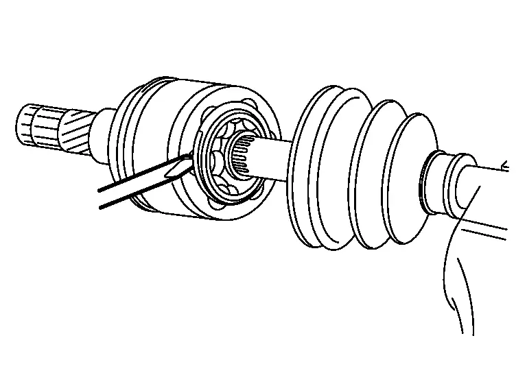
Put matching marks on ball cage/steel ball/inner race assembly and shaft.
CAUTION:
Use paint or similar substance for matching marks. Never scratch the surface.
Remove snap ring, then remove ball cage/steel ball/inner race assembly from shaft.
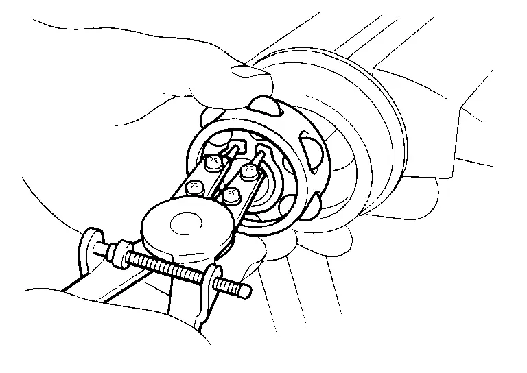
Remove boot from shaft.
Perform inspection after disassembly. Refer to Inspection.
ASSEMBLY
Remove old grease on housing with paper waste.
Install boot and boot bands to shaft.
CAUTION:
Wrap serration on shaft with tape
 to protect the boot from damage.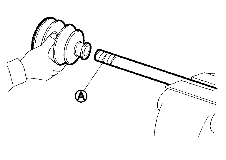
Never reuse boot and boot band.
Remove the tape wrapped around the serration on shaft.
Install ball cage/steel ball/inner race assembly  , align it with the matching marks on shaft
  put during the removal.
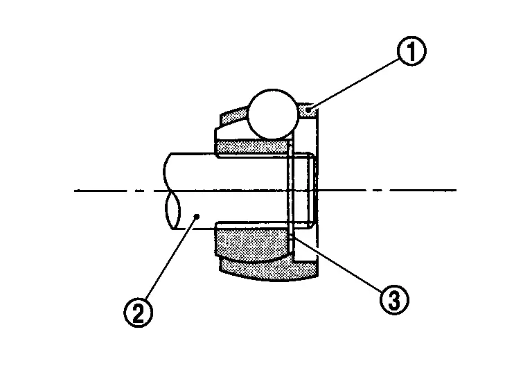
Secure ball cage/steel ball/inner race assembly onto shaft with snap ring  .
.
CAUTION:
Never reuse snap ring.
Apply the appropriate amount of grease onto housing and sliding surface.
| Grease amount | Drive Shaft |
Install housing to shaft.
Install stopper ring to housing.
CAUTION:
Never reuse stopper ring.
After installed, pull shaft to check engagement between housing and stopper ring.
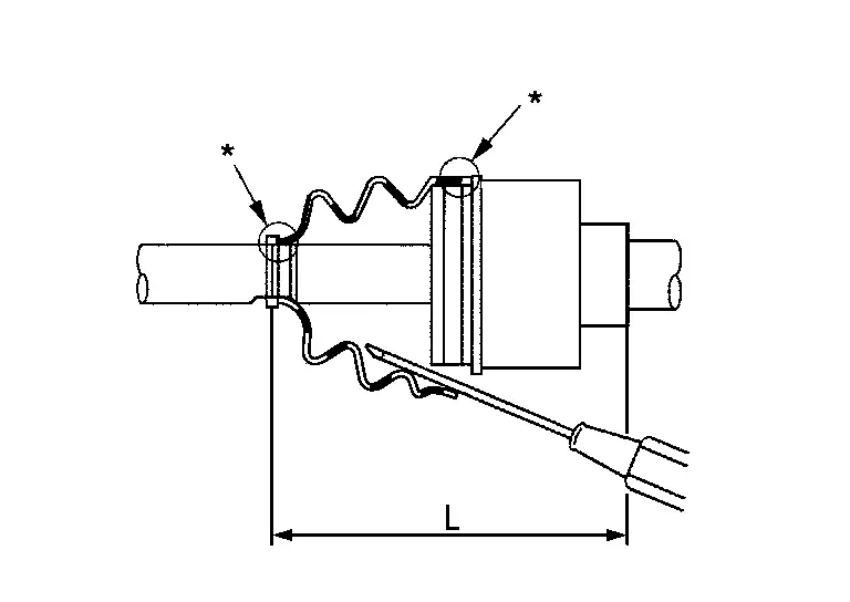
Install boot securely into grooves (indicated by “*� marks) shown in the figure.
CAUTION:
If grease adheres to the boot mounting surfaces (indicated by “*� marks) on shaft or housing, boot may be removed. Remove all grease from the surfaces.
To prevent deformation of the boot, adjust the boot installation length (L) to the value shown below by inserting the suitable tool into the inside of boot from the large diameter side of boot and discharging inside air.
| L | Drive Shaft |
CAUTION:
If the boot installation length is outside the standard, it may cause breakage of boot.
Be careful not to touch the inside of the boot with the tip of tool.
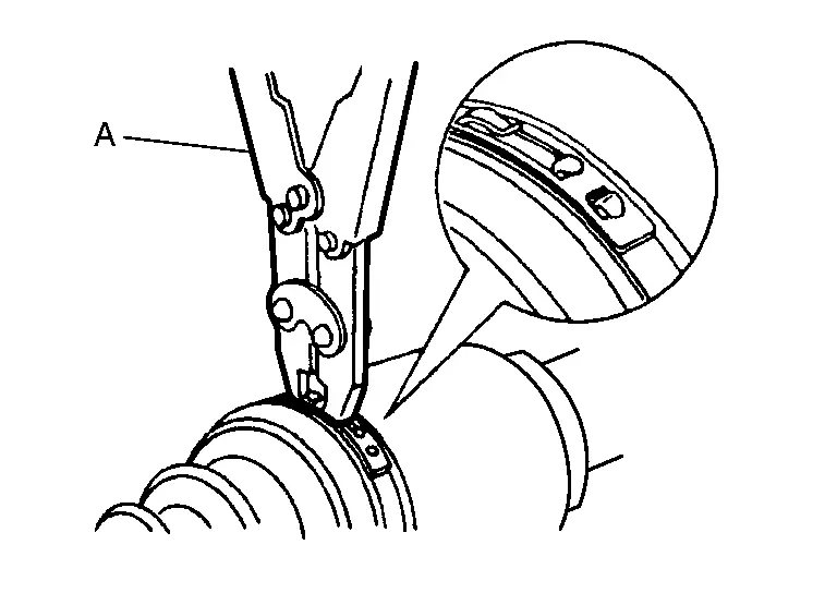
Secure the large and small ends of the boot with boot bands using the boot band crimping tool [SST: KV40107300 (NI-51751)] (A).
CAUTION:
Never reuse boot band.
 NOTE:
NOTE:
Secure boot band so that dimension (M) meets the specification as shown in the figure.
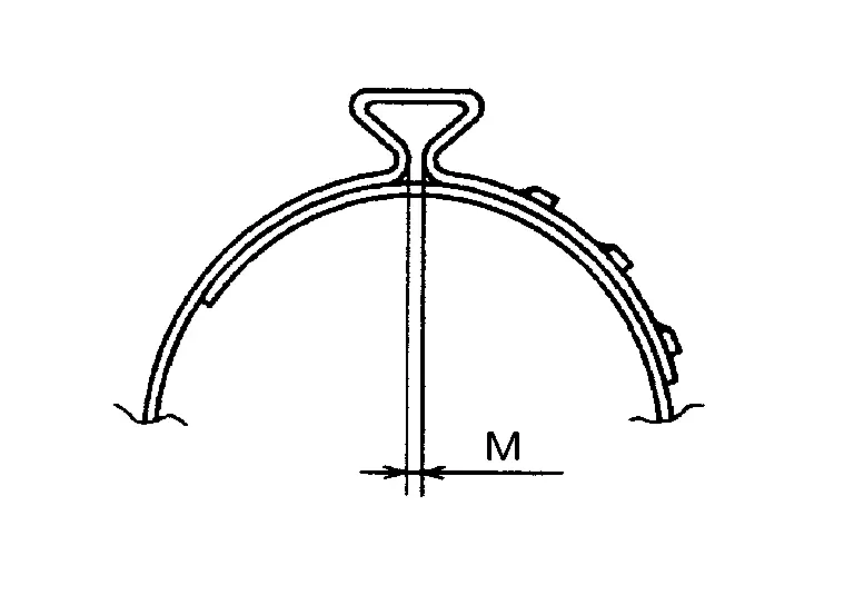
| M | : 1.0 – 4.0 mm (0.039 – 0.157 in) |
Secure housing and shaft, and then check that they are in the correct position when rotating boot. Install them with boot band when the mounting positions become incorrect.
CAUTION:
Never reuse boot band.
Install dust shield to housing.
CAUTION:
Never reuse dust shield.
Install circular clip to housing.
CAUTION:
Never reuse circular clip.
DISASSEMBLY
Fix shaft with a vise.
CAUTION:
Protect shaft when fixing with a vise using aluminum or copper plates.
Remove dust shield from joint sub-assembly.
Remove boot bands and then remove boot from joint sub-assembly.
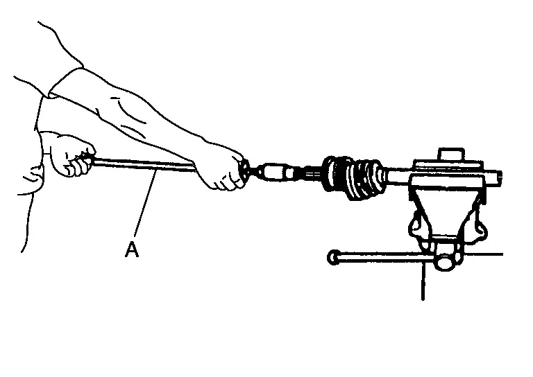
Screw the drive shaft puller (commercial service tool) (A) 30 mm (1.18 in) or more into the thread of joint sub-assembly, and pull joint sub-assembly from shaft.
CAUTION:
If joint sub-assembly cannot be removed after five or more unsuccessful attempts, replace shaft and joint sub assembly as a set.
Align drive shaft puller and drive shaft and remove them by pulling directory.
Remove circular clip from shaft.
Remove boot from shaft.
Perform inspection after disassembly. Refer to Inspection.
ASSEMBLY
While rotating ball cage, clean old grease on joint sub-assembly with paper waste.
Fill serration slot joint sub-assembly with NISSAN genuine grease or equivalent until the serration slot and ball groove become full to the brim.
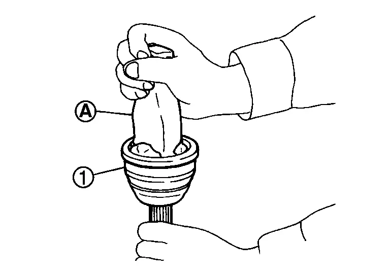
CAUTION:
After applying grease, use a shop cloth to wipe off old grease that has oozed out.
Install boot and boot bands to shaft.
CAUTION:
Wrap serration on shaft with tape
to protect the boot from damage.Never reuse boot and boot band.
Remove the tape wrapped around the serration on shaft.
Position circular clip on groove at the shaft edge.
CAUTION:
Never reuse circular clip.
NOTE:
Drive joint inserter is recommended when installing circular clip.
Align both center axles of the shaft edge and joint sub-assembly. Then assemble shaft with joint sub-assembly holding circular clip.
Install joint sub-assembly to shaft using plastic hammer.
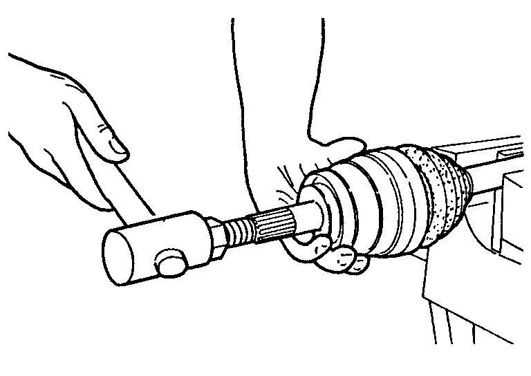
WARNING:
Pull the joint sub-assembly in the axial direction away from transaxle assembly. Confirm that the joint sub assembly cannot be pulled out.
Apply the specified amount of grease into the boot inside from large diameter side of boot.
| Grease amount | Drive Shaft |
Install the boot securely into grooves (indicated by “*� marks) shown in the figure.
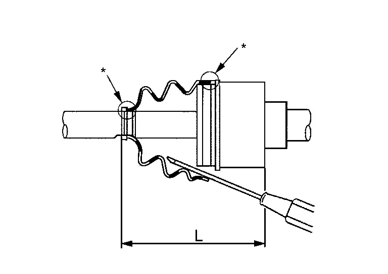
CAUTION:
If grease adheres to the boot mounting surface (indicated by “*� mark) on the shaft or housing, boot may come off. Remove all grease from the surfaces.
To prevent the deformation of the boot, adjust the boot installation length (L) to the specified value shown below by inserting the suitable tool into inside of the boot from the large diameter side of boot and discharging the inside air.
| L | Drive Shaft |
CAUTION:
If the boot installation length is outside the standard, it may cause breakage of boot.
Be careful not to touch the inside of the boot with the tip of tool.
Install new boot bands securely.
CAUTION:
Never reuse boot band.
Small boot bandSecure the ends of the boot with boot bands using the boot band crimping tool [SST: KV40107300 (NI-51751)] (A).
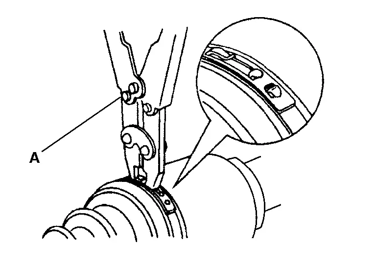
CAUTION:
Secure boot band so that dimension (M) meets the specification as shown in the figure.
M : 1.0 – 4.0 mm (0.039 – 0.157 in)
CAUTION:
Never reuse boot band.
Set boot band to the drive shaft boot groove and temporarily fix pawl
of boot band to  of boot band.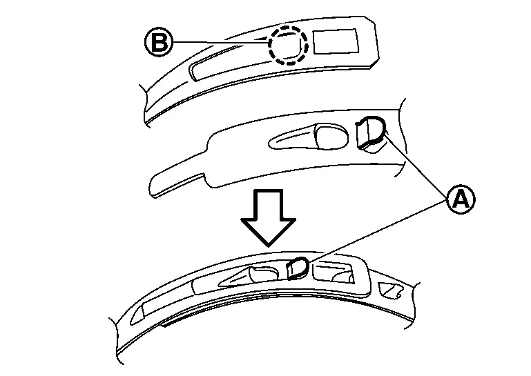
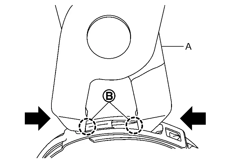
Pull protrusion of boot band tighten with boot band crimping tool [SST: KV40107310 (-)] (A) in the direction shown by arrows (
 ).
).
CAUTION:
Securely install boot band
to boot band pawl .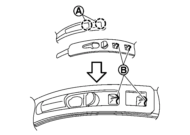
Secure joint sub-assembly and shaft, and then check that they are in the correct position when rotating boot. Install them with boot band when boot installation positions become incorrect.
CAUTION:
Never reuse boot band.
Install dust shield to joint sub-assembly.
CAUTION:
Never reuse dust shield.
 Removal and Installation
WARNING:
REMOVAL
Remove engine under cover. Refer to Removal and Installation
Drain A/T fluid. Refer to Draining.
Remove tires. Refer to ROAD WHEEL TIRE : Removal & Installation.
Remove front whee ...
 Inspection
INSPECTION AFTER REMOVAL
Move joint up/down, left/right, and in the axial directions. Check for motion that is not smooth and for significant looseness.
Check boot for cracks, damage, and leakage of g ...
Other materials:
Inspection
WARNING:
LOOSENESS OF CONNECTED PART
Check each fixing bolt and nut for looseness using torque wrench. For each tightening torque, refer to Exploded View.
BACKLASH OF JOINT PART
BACKLASH OF CENTER BEARING
Move the shaft near center bearing up and down and from side to side (axial direction of shaft ...
Tire Pressure Monitoring System (TPMS)
Basic information
For optimal safety and performance of your Nissan Armada, each tire—including
the spare tire (if equipped)—should be inspected at least once a month when cold
and inflated according to the manufacturer’s recommended pressure values listed
on the vehicle placard or tire ...
System maintenance (ProPILOT Assist 2.1)
For reliable and accurate operation of the Nissan Armada ProPILOT Assist 2.1
system, it is crucial to keep the driver monitoring area clean and free from any
obstruction at all times.
Regularly inspect the camera surface and gently remove dust, fingerprints, or
any debris using a soft, cl ...

0.0057