Exploded View
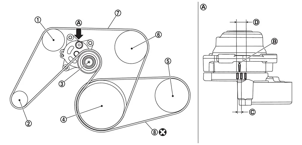
 |
Idler pulley |  |
Alternator |  |
Drive belt auto-tensioner |
 |
Crankshaft pulley |  |
A/C compressor |  |
Water pump |
 |
Drive belt |  |
A/C compressor belt | ||
 |
View |  |
Indicator |  |
Range when new drive belt is installed |
 |
Possible use range | ||||
 |
Always replace after every disassembly. |
Removal & Installation
WARNING:
-
Jacking up or lift up the vehicle may the vehicle height to go down which cause a personal injury and/or damage to the air suspension component parts. Refer to Precaution for when Jacking and Lifting Up the vehicle with Electronic Air Suspension System.
-
When checking under the vehicle or inside wheel house, always turn OFF the electronic air suspension function with the vehicle unladen and normal height, since the suspension may accidentally move and it can lead to personal injury. Refer to Precaution for Electronic Air Suspension System.
REMOVAL
Drive belt
Remove front under cover, using a power tool (commercial service tool). Refer to Removal and Installation.
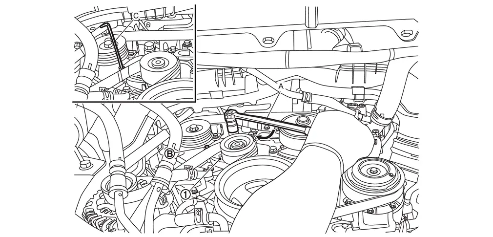
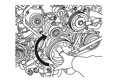
While securely holding the hexagonal part of drive belt auto-tensioner with a spinner handle (A), move spinner handle in the direction of arrow (loosening direction of drive belt).
CAUTION:
Never place hand in a location where pinching may occur if the holding tool accidentally comes off.
|
: Holding boss |
| C | : Metallic bar [approximately 6 mm (0.24 in) in diameter]* |
 |
: Loosening direction of drive belt |
*: Hexagonal wrench shown as example in the figure
Under the above condition, insert a metallic bar through the holding boss to lock drive belt auto-tensioner pulley arm.
Remove drive belt.
A/C compressor belt
Remove front under cover, using a power tool (commercial service tool). Refer to Removal and Installation.
Remove drive belt.
Cut A/C compressor belt.
INSTALLATION
Drive belt
Note the following, and install in the reverse order of removal.
CAUTION:
-
Check drive belt is securely installed around all pulleys.
-
Check drive belt is correctly engaged with the pulley groove.
-
Check for engine oil and engine coolant are not adhered drive belt and pulley groove.
A/C compressor belt
Install A/C compressor belt as shown below.
CAUTION:
Check for engine oil and engine coolant are not adhered A/C compressor belt and pulley groove.
 NOTE:
NOTE:
Stretch belt service tool is enclosed when A/C compressor belt is ordered.
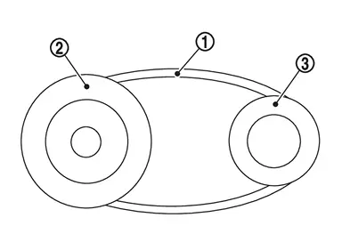
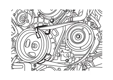
Attach A/C compressor belt to crankshaft pulley
  and A/C compressor as shown in the figure.
-
Install A/C compressor belt
between the crankshaft pulley on the crankshaft side and the engine assembly .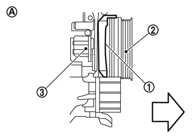
: vehicle front : Side view -
Install A/C compressor belt
to the A/C compressor .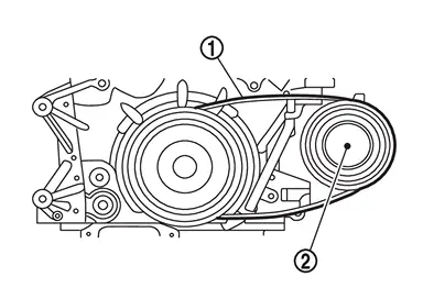
CAUTION:
-
Make sure that the back side
of the A/C compressor belt faces the engine side.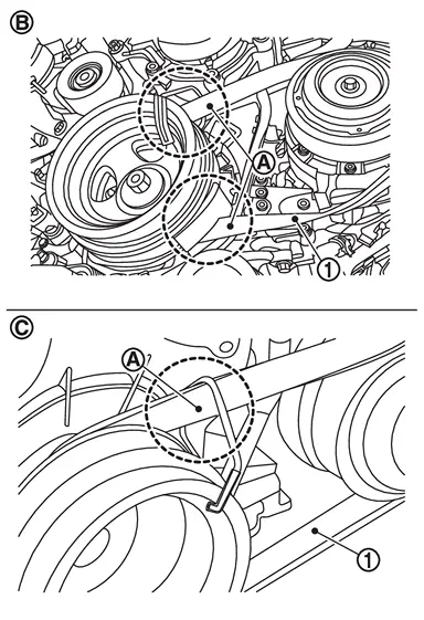
: OK : NG
-
Do not reverse the installation position of the service tool (A).
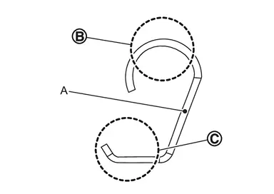
: A/C compressor belt side : Crankshaft pulley side
-
When installing to the crankshaft pulley, make sure that the crankshaft pulley protection tube
of the service tool (A) is not inserted too far.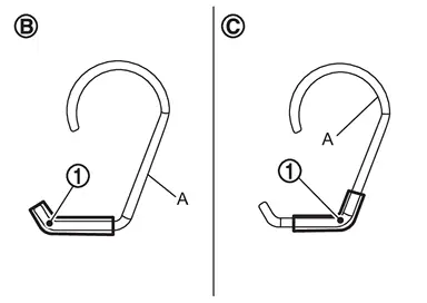
: OK : NG
NOTE:
-
Set the service tool (A) as shown below.
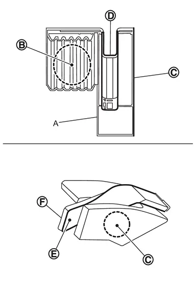
: Crankshaft pulley side : Engine side : Belt install part 
: Belt back side 
: Belt groove side
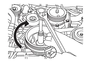
CAUTION:
-
When rotating the crankshaft pulley by applying a tool to the crankshaft pulley bolt, do not turn the crankshaft pulley bolt in the direction of loosening.
-
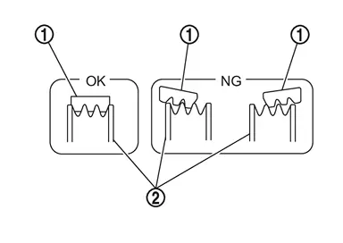
Referring to the figure, check that the A/C compressor belt
is securely attached around the crankshaft pulley .
: OK (Installed correctly.) : NG (A/C compressor belt is misaligned (C) with the groove of the crankshaft pulley.)
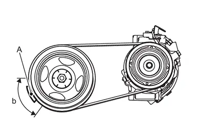
) while making sure that the A/C compressor belt is not misaligned with the pulley groove.
CAUTION:
Check A/C compressor belt is correctly engaged with the pulley groove.
When the service tool (A) is in position (B), remove the service tool (C).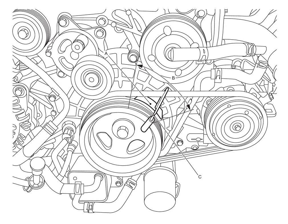
CAUTION:
-
Be careful not to damage the belt when removing the mounting tool.
-
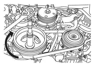
Check A/C compressor belt is securely installed around crankshaft pulley and A/C compressor.
: A/C compressor belt : A/C compressor/ Crankshaft pulley
Adjustment
Refer to Drive Belt.
Inspection
WARNING:
-
Jacking up or lift up the vehicle may the vehicle height to go down which cause a personal injury and/or damage to the air suspension component parts. Refer to Precaution for when Jacking and Lifting Up the vehicle with Electronic Air Suspension System.
INSPECTION BEFORE REMOVAL
Drive belt
WARNING:
Be sure to perform the this step when engine is stopped.
-
Check that the indicator (notch on fixed side) of drive belt auto-tensioner is within the possible use range.
NOTE:
Check the drive belt auto-tensioner indication when the engine is cold.
-
Visually check the entire drive belt for wear, damage or crack.
-
If the indicator (notch on fixed side) is out of the possible use range or belt is damaged, replace drive belt.
A/C compressor belt
WARNING:
Perform this step when engine is stopped.(30 min or longer after engine is stopped)
-
Visually check entire drive belt for wear, damage or cracks.
-
Using a tensiometer and confirm belt tension or vibration frequency value.
NOTE:
Before measuring, turn crankshaft pulley twice.
-
Measure belt
tension at " " points. (Both side measurement are correct)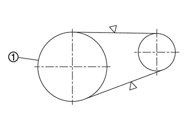
-
Confirm the belt tension value or the vibration frequency value. (see table below)
Belt tension Frequency 580 - 1327 N 192 - 292 Hz
INSPECTION AFTER INSTALLATION
Drive belt
-
Turn crankshaft pulley clockwise several times to equalize tension between each pulley, and then confirm tension of drive belt at indicator (notch on fixed side) is within the possible use range. Refer to Exploded View.
Other materials
I-BSI system limitations
WARNING
The following limitations apply to the Nissan Armada Intelligent Blind Spot
Intervention (I-BSI) system. Failure to operate the vehicle within these limitations
may result in serious injury or death.
The Nissan Armada I-BSI system cannot detect all vehicles or objects
in every si ...
Heater & Air Conditioning System Service Data and Specifications
A/C compressor
Model
DENSO make
7SAS17C
Type
Variable displacement swash plate
Displacement
cm3 (cu in)/rev
Maximum
170 (10.4)
Direction of rotation
Clockwise (viewed from clutch)
Drive belt
Poly V
Lubricant
Name
ND-OIL12 (PAG)
Capacity
m (US fl oz, Imp fl oz)
To ...
Display Screen Is Not Displayed (information Display)
Diagnosis Procedure
PERFORM SELF-DIAGNOSIS OF DISPLAY UNIT
Perform “Self Diagnostic Result” of “Display unit”.
Is DTC detected?
YES>>
Perform diagnosis procedure on the detected DTC. Refer to DTC Index.
NO>>
GO TO 2.
PERFORM SELF-DIAGNOSIS OF COMBINATION METER
Perform “Self D ...