Exploded View
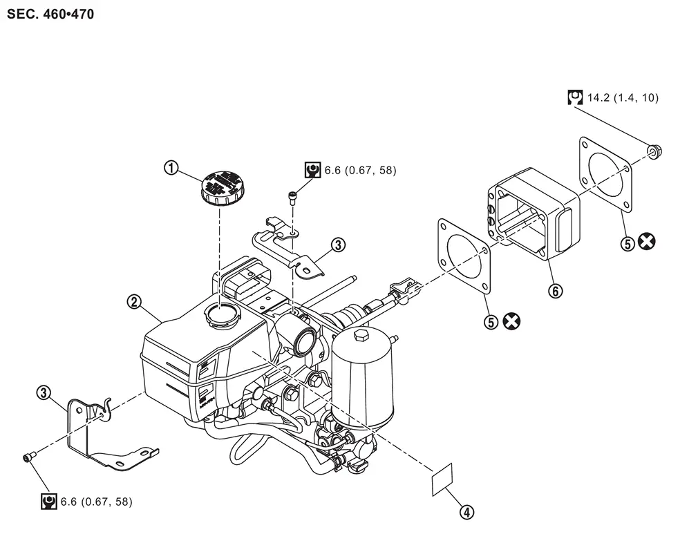
 |
Reservoir cap |  |
Electrical brake control unit |  |
Bracket |
 |
Caution label |  |
Gasket |  |
Spacer |
 |
: N·m (kg-m, ft-lb) | ||||
 |
: N·m (kg-m, in-lb) | ||||
 |
: Always replace after every disassembly. | ||||
Removal & Installation
WARNING:
-
Jacking up or lift up the vehicle may the vehicle height to go down which cause a personal injury and/or damage to the air suspension component parts. Refer to Precaution for when Jacking and Lifting Up the vehicle with Electronic Air Suspension System.
REMOVAL
CAUTION:
-
While electrical brake control unit
is removed, hold part  with hand.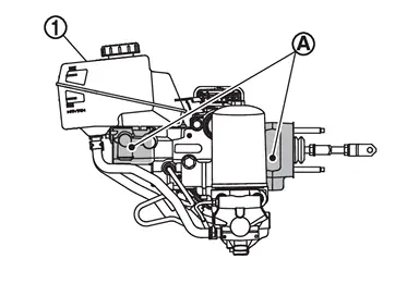
-
Never disassemble electrical brake control unit.
-
Never spill or splash brake fluid on painted surfaces. Brake fluid may seriously damage paint. Wipe it off immediately and wash with water if it gets on a painted surface.
-
Never depress brake pedal during removal and installation of brake hose because brake fluid may scatter.
Perform inspection before removal. Refer to Inspection.
Perform the advance preparation "(Air release) Accumulator pressure release" using CONSULT. Refer to Work Procedure.
Ignition switch OFF and disconnect CONSULT from DDL2 diagnosis connector.
Get out of the vehicle, close all doors (other than hood assembly), check that the combination meter is OFF, and wait for 1 minute or more without opening these doors.
CAUTION:
Never operate the vehicle.
Disconnect negative terminal of 12V battery. Refer to Precautions for Removing Battery Terminal.
Drain brake fluid. Refer to Draining.
Disconnect electrical brake control unit harness connector , follow the procedure below.
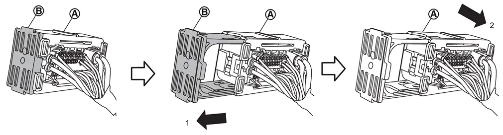
 of the connector toward the direction (1). Disconnect electrical brake control unit harness connector to ward the direction (2).
Disconnect accumulator harness connector, and remove harness clip from electrical brake control unit.
Remove relay box.
Remove brake tubes from electrical brake control unit and ABS actuator and electric unit (control unit).
Move heater hose. Fix heater hose in a place where it will not interfere with work.
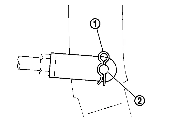
Remove snap pin and clevis pin from clevis.
Remove electrical brake control unit mounting nut.
Remove electrical brake control unit from vehicle.
CAUTION:
Never deform the brake tube when removing electrical brake control unit.
Remove gaskets and spacer from electrical brake control unit.
Remove brackets from electrical brake control unit if necessary.
Perform inspection after removal. Refer to Inspection.
INSTALLATION
CAUTION:
When installing electrical brake control unit, never deform brake tube.
-
If electrical brake control unit is dropped or impacted, replace electrical brake control unit assembly.
-
When installing, hold part
of electrical brake control unit . -
Never apply grease or lubricant to the parts that contact with brake fluid and rubber parts.
-
Never spill or splash brake fluid on painted surfaces. Brake fluid may seriously damage paint. Wipe it off immediately and wash with water if it gets on a painted surface.
-
Never depress brake pedal during removal and installation of brake hose because brake fluid may scatter.
Note the following, and install in the reverse order of removal.
-
Never crush threads of stud bolts of the electrical brake control unit. When installing diagonally, the dash panel may damage the threads.
-
Never deform brake tube when installing electrical brake control unit.
-
Never reuse clevis pin.
-
Temporarily tighten flare nut of brake tube
by hand, and then install it to the electrical brake control unit to the specified tightening torque using flare nut torque wrench (commercial tool) (A). Refer to Exploded View.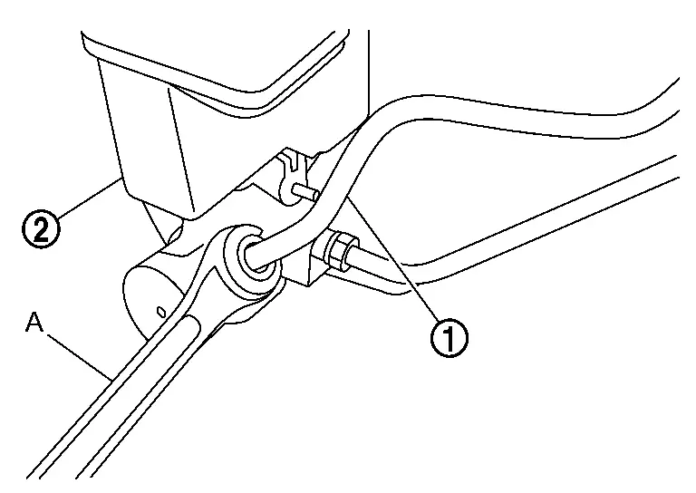
-
Install electrical brake control unit harness connector
, follow the procedure below.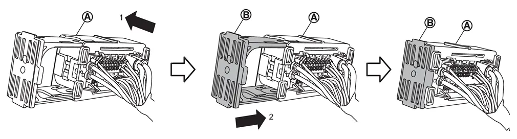
-
Install electrical brake control unit harness connector toward the direction (1).
-
Push the lock
of the connector toward the direction (2).
-
-
Perform air bleeding. Refer to Work Procedure.
-
Check brake pedal for each item, adjust when there is deviation from the specified value. Refer to Inspection and Adjustment.
-
Perform inspection after installation. Refer to Inspection.
-
After replacing the electrical brake control unit, always follow the disposal procedure to discard the electrical brake control unit. Refer to Disposal.
Inspection
INSPECTION BEFORE REMOVAL
Check brake fluid level switch. Refer to Brake Fluid Level Switch.
INSPECTION AFTER REMOVAL
Check the following items, and replace the part if necessary.
-
Check for damage, deformation, interference with the other parts, and looseness of connection.
-
Check for fluid leakage from connection. Refer to Inspection.
CAUTION:
When fluid leakage is occurred, tighten each bolt to the specified torque. Replace parts if there is still leakage.
-
Check the input rod length (A). If the length of the input rod is outside the standard value, replace the electrical brake control unit.
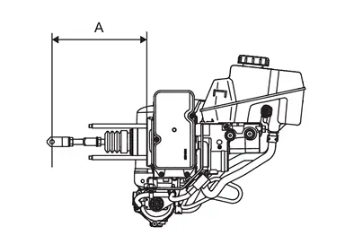
Input rod length (A): Refer to Electrical Brake Control Unit.
INSPECTION AFTER INSTALLATION
-
If replacing electrical brake control unit, perform "ADDITIONAL SERVICE WHEN REPLACING ELECTRICAL BRAKE CONTROL UNIT". Refer to Work Procedure.
-
Perform stroke sensor calibration when electrical brake control unit removed and installed, or replaced. Refer to Work Procedure.
Disposal
Fix the electrical brake control unit to a vise.
CAUTION:
-
Always set copper plates or cloth between vise grips when fixing the electrical brake control unit to a vise.
-
Never overtighten the vise.
Make a slit in the area (A) with a saw to release filler gas.
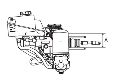
| A | : 50 mm (1.97 in) |
CAUTION:
-
Wear eye protection (safety glasses).
-
Wear gloves.
-
A cut in the area must be made perpendicularly.
-
Perform the procedure slowly.
-
Cover with cloth to avoid sawdust to spatter.
 NOTE:
NOTE:
The gas is clear colorless, odorless, and harmless.
Other materials
Rear Blower Motor
Exploded View
Rear A/C unit assembly
Rear blower motor
: vehicle front
Removal and Installation
REMOVALRemove rear A/C unit assembly. Refer to Removal and Installation.
Disconnect rear blower unit harness connector.
Remove fixing screws , and then remove rear blower motor. ...
Body Construction
Body Construction
Outer side body
Outer front pillar reinforcement
Upper front pillar reinforcement
Upper inner front pillar
Side dash reinforcement (Upper)
Upper side dash
Weld nut
Upper hinge plate
Hoodledge reinforcement
Upper front pillar hinge brace
Side dash ...
Precautions
Precaution for Supplemental Restraint System (SRS) "AIR BAG" and "SEAT BELT PRE-TENSIONER"
The Supplemental Restraint System such as “AIR BAG” and “SEAT BELT PRE-TENSIONER”, used along with a front seat belt, helps to reduce the risk or severity of injury to the driver and front passenger fo ...