Removal and Installation
CAUTION:
-
Perform work with 2 workers, because it is heavy weight.
-
Support door with a proper material and use protective tape or shop cloth to protect door and body from falling and damage when removing and installing door assembly.
REMOVAL
Remove front door check link mounting bolt of vehicle body side.
Disengage pawl  of front door harness connector, and then release lock release lever
  according to numerical order 1→2 indicated by arrows as shown in figure and disconnect front door harness connector.
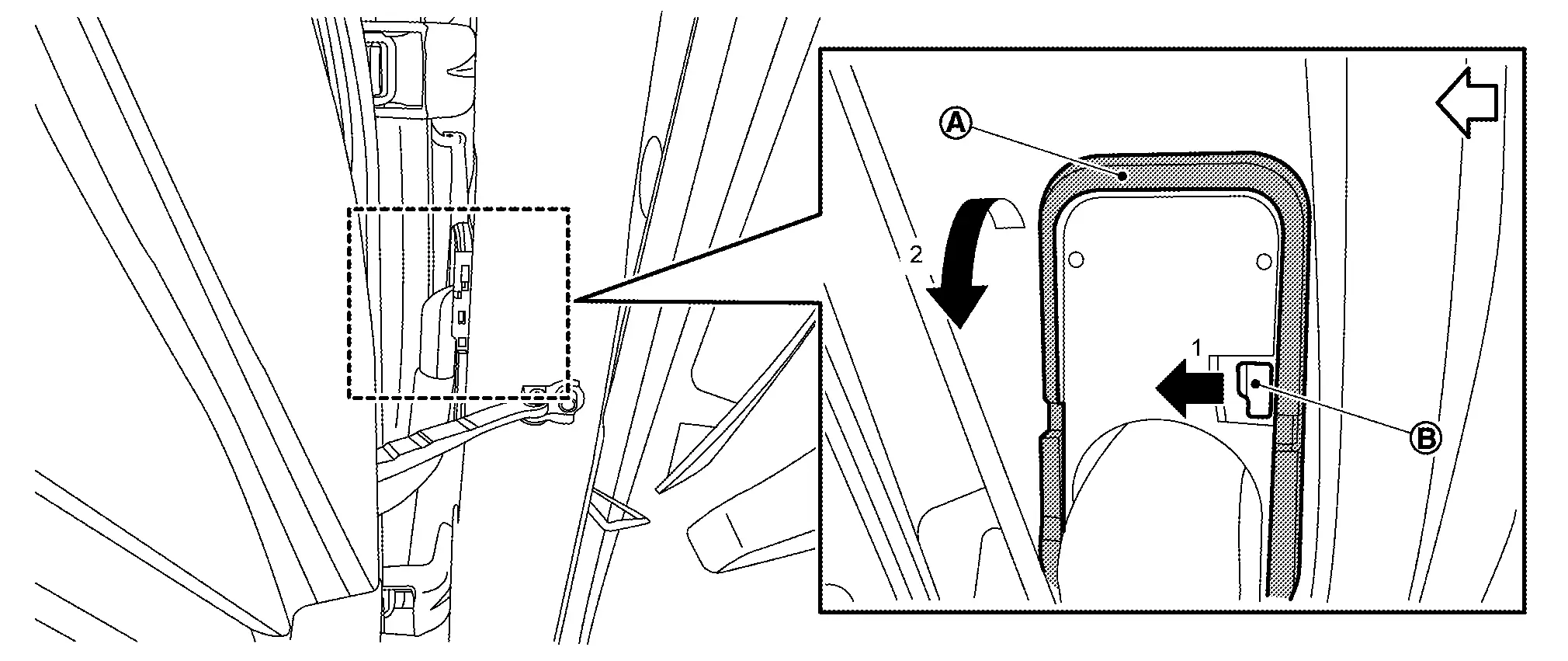
| : vehicle front |
Support front door assembly with a proper material to prevent it from falling.
WARNING:
Injury may occur if door assembly is not supported with a proper material when removing front door assembly.
Remove front door hinge mounting nuts, and then remove front door assembly.
INSTALLATION
Note the following items, and then install in the reverse order of removal.
CAUTION:
-
Before installation, apply anticorrosive agent onto mounting surface.
-
When installation, perform the fitting adjustment. Refer to Adjustment.
-
After installation, apply touch-up paint (the body color) onto the head of front door hinge mounting nuts.
-
After installation, check the open/close operation. Refer to Inspection.
-
After installation, apply anticorrosive around the nuts to prevent rust.
Inspection
Open and close front door. Check that front door hinge and front door check link rotation portion moves smoothly.
Check front door hinge rotating part for lubrication condition. Apply body grease if necessary.
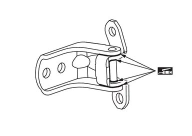
 |
: Body grease |
Check front door check link rotating part for lubrication condition. Apply body grease if necessary.
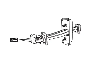
|
: Body grease |
Adjustment
FITTING ADJUSTMENT
Fitting Adjustment Standard Dimension
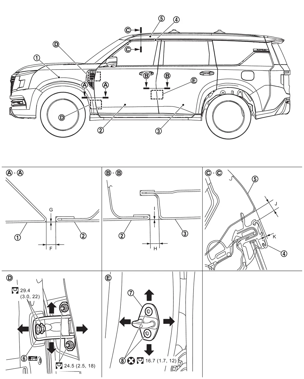
 |
Front fender assembly |  |
Front door panel |  |
Rear door panel |
 |
Front door sash molding |  |
Body side outer |  |
Front door hinge |
 |
Front door striker |  |
TORX bolt | ||
 |
: Always replace after every disassembly. | ||||
 |
: N·m (kg-m, ft-lb) | ||||
|
: Body grease | ||||
Unit: mm [in]
| Portion | Standard | |||
|---|---|---|---|---|
| Front door panel – Front fender assembly | – |
F | Clearance |
4.5 ± 1.0 [0.177 ± 0.039] |
| G | Surface height |
0.0 ± 1.0 [0.000 ± 0.039] |
||
| Front door panel – Rear door panel | – |
H | Clearance |
4.5 ± 1.0 [0.177 ± 0.039] |
| I | Surface height |
0.0 ± 1.0 [0.000 ± 0.039] |
||
| Front door sash molding – Body side outer |  – – |
J | Clearance |
7.3 ± 1.8 [0.287 ± 0.071] |
| K | Surface height |
0.6 ± 1.9 [0.024 ± 0.075] |
||
Check the clearance and surface height between front door and each part by visually and touching.
If the clearance and the surface height are out of specification, adjust them according to the procedures shown below.
Fitting Adjustment Procedure
Remove front door assembly. Refer to Removal and Installation.
Loosen front door hinge mounting bolts.
Temporary install front door panel, and then adjust the clearance of front door according to the fitting adjustment standard dimension by moving front door panel.
Remove temporary install parts, and then tighten front door hinge mounting bolts to the specified torque.
CAUTION:
-
When remove front door panel, never move front door hinge.
-
After tightening, apply touch-up paint (the body color) onto the head of hinge mounting bolts.
Install front door assembly, and then temporary tighten front door hinge mounting nuts. Refer to Removal and Installation.
Adjust the surface height of front door according to the fitting adjustment standard dimension by moving front door panel.
Tighten front door hinge mounting nuts to the specified torque.
CAUTION:
-
After tightening, apply touch-up paint (the body color) onto the head of hinge mounting nuts.
-
After installation, apply anticorrosive around the bolts and nuts to prevent rust.
-
After adjusting, perform the camera calibration (with around view monitor models). Refer to Work Procedure.
FRONT DOOR STRIKER ADJUSTMENT
Adjust front door striker so that it becomes parallel with door lock insertion direction.
Other materials
Basic information
WARNING
In the Nissan Armada, radio frequency signals emitted by the Intelligent
Key system may interfere with certain medical devices.
Individuals using pacemakers or similar medical equipment should consult
the device manufacturer to determine possible effects before using the Nissa ...
Outside mirrors
Basic information
WARNING
Objects reflected in the passenger-side outside mirror of the Nissan Armada
may appear farther away than they actually are. Always exercise caution when changing
lanes to the right. Relying solely on the mirror can lead to misjudgment and potential
accidents. For ma ...
Diagnosis and Repair Workflow
Work Flow
OVERALL SEQUENCEDETAILED FLOWINTERVIEW FOR MALFUNCTION
It is also important to clarify the customer concerns before starting the inspection. Interview the customer about the concerns carefully and understand the symptoms fully.
NOTE:
The customers are not professionals. Never assume that â ...