Exploded View
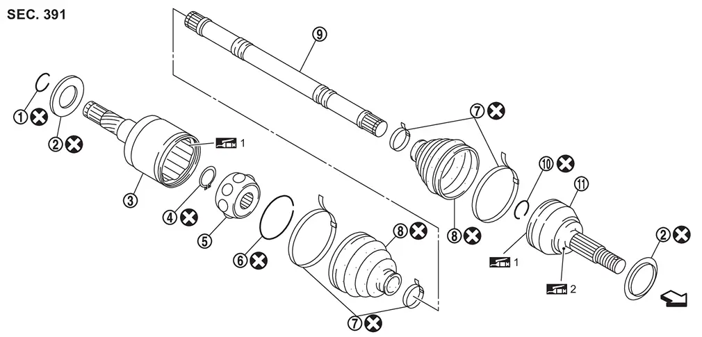
Removal and Installation
WARNING:
-
Jacking up or lift up the vehicle may the vehicle height to go down which cause a personal injury and/or damage to the air suspension component parts. Refer to Precaution for when Jacking and Lifting Up the vehicle with Electronic Air Suspension System.
REMOVAL
Remove engine under cover. Refer to Removal and Installation
Drain A/T fluid. Refer to Draining.
Remove tires. Refer to ROAD WHEEL TIRE : Removal & Installation.
Remove front wheel sensor from steering knuckle. Refer to Removal and Installation.
Remove brake caliper assembly. Hang brake caliper assembly in a place where it will not interfere with work. Refer to FRONT BRAKE CALIPER ASSEMBLY : Removal & Installation.
CAUTION:
Never depress brake pedal while brake caliper is removed.
Remove disc rotor.
CAUTION:
-
Put matching marks
 on the wheel hub assembly and the disc rotor before removing the disc rotor.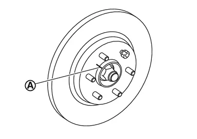
-
Never drop disc rotor.
Remove brake hose bracket from steering knuckle.
Using lock nut chisel [SST: KV40108800 (NI-52982)] (A), release stacked area of wheel hub lock nut.
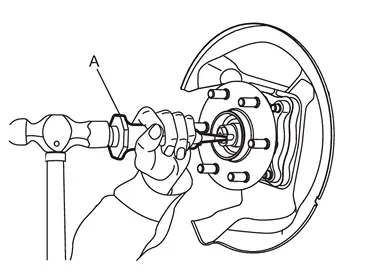
CAUTION:
-
Completely release the caulking part of the wheel hub lock nut.
-
Never add damage to the driveshaft side screw thread with wheel hub lock nut.
 NOTE:
NOTE:
Stacked area is about (A) of the wheel hub lock nut should be widened 34 mm (1.34 in) or more.
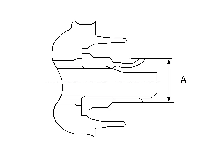
Loosen wheel hub lock nut, using a hub lock nut wrench [SST: KV40104001 (NI-53385)] (A).
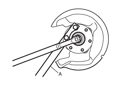
CAUTION:
-
Never use a power tool.
-
When rotation of locknut does not turn smoothly, release stacked area is performed again.
Separate upper link from steering knuckle, using the ball joint remover (commercial service tool), and remove upper link.
CAUTION:
-
Temporarily tighten the nut to prevent damage to threads and to prevent the ball joint remover from suddenly coming off.
-
Never damage ball joint boot.
Set suitable jack under lower link.
Remove steering outer socket. Refer to Removal and Installation.
Remove lower link from steering knuckle.
CAUTION:
Never damage ball joint boot.
Remove steering knuckle.
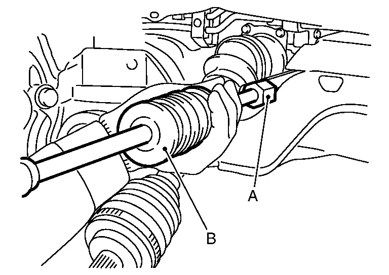
Remove drive shaft from front final drive assembly.
-
Use the drive shaft attachment [SST: KV40107500 ( − )] (A) and a sliding hammer (commercial service tool) (B) while inserting tip of the drive shaft attachment between housing and front final drive assembly.
CAUTION:
-
Never place drive shaft joint at an extreme angle when removing drive shaft. Also be careful not to overextend slide joint.
-
Confirm that the circular clip is attached to the drive shaft.
-
INSTALLATION
Note the following, and install in the reverse order of removal.
CAUTION:
Always replace front final drive assembly side oil seal with new one when installing drive shaft. Refer to Removal and Installation.
-
Place the protector [SST: KV38107900 (NI-33904) (NI-52469-1)] (A) onto front final drive assembly to prevent damage to the front final drive assembly side oil seal while inserting drive shaft. Slide drive shaft sliding joint and tap with a hammer to install securely.
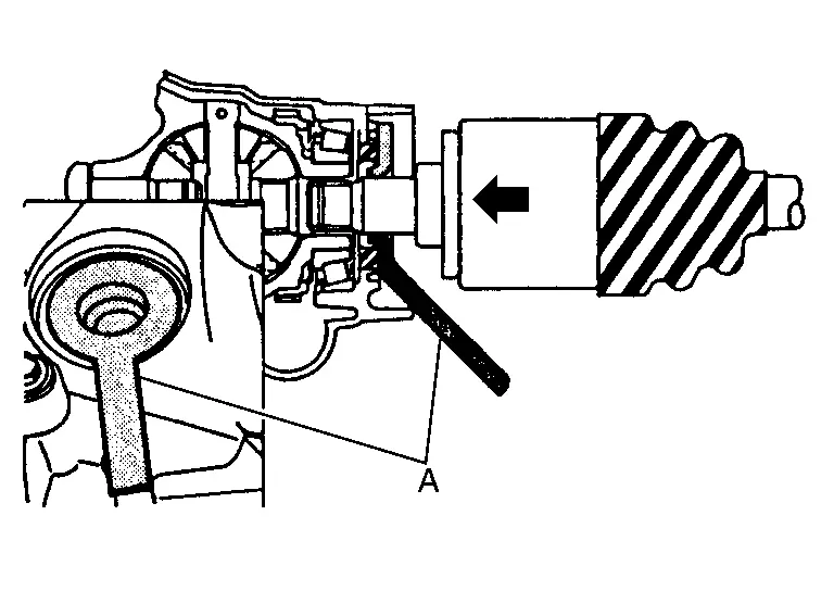
CAUTION:
-
Be sure to fully install the protector into the depths of the part.
-
When inserting the protector, be careful not to remove the grease.
-
When inserting the drive shaft, be careful not to let the splined part of the drive shaft touch the lip of the oil seal.
WARNING:
Ensure that circular clip is properly engaged, otherwise the joint sub-assembly could pull away from transaxle during vehicle operation resulting in loss of drive force and possible drive shaft damage, which may cause a crash and serious injury or damage the drive shaft.
CAUTION:
-
To ensure the circular clip is properly engaged, grasp the housing
 and pull back and forth in axial direction while listening for clicking sounds.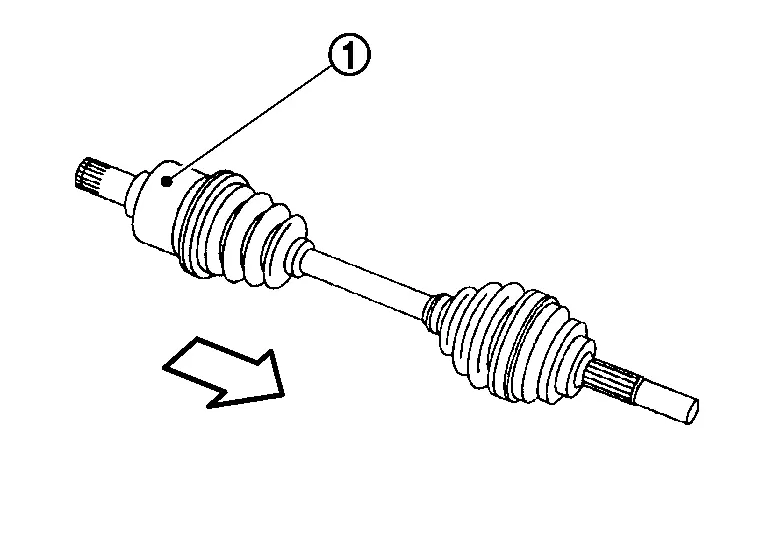
: Wheel side -
Pull the joint sub-assembly in the axial direction away from front final drive assembly (arrow). Confirm that the joint sub assembly cannot be pulled out.
-
-
Clean the matching surface of wheel hub lock nut and wheel hub and bearing assembly.
CAUTION:
Never apply lubricating oil to these matching surface.
-
Clean the matching surface of drive shaft and wheel hub and bearing assembly. And then apply paste [service parts (440037S000)] to surface
of joint sub-assembly of drive shaft.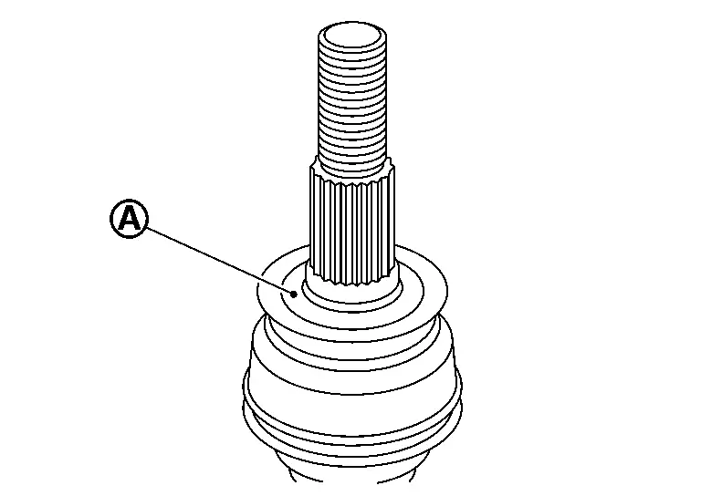
CAUTION:
Apply paste to cover entire flat surface of joint sub-assembly of drive shaft.
Amount paste : 1.0 – 3.0 g (0.04 – 0.10 oz) -
Insert drive shaft to wheel hub, and then temporarily tighten hub lock nut.
CAUTION:
Never overlap drive shaft stacked area
and wheel hub bolts .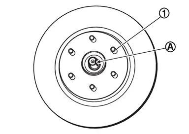
-
Tighten the wheel hub lock nut to the specified torque.

: 218 - 223 N·m (22 - 23 kg-m, 161 - 164 ft-lb) CAUTION:
-
Since the drive shaft is assembled by press-fitting, use the tightening torque range for the wheel hub lock nut.
-
Be sure to use torque wrench to tighten the wheel hub lock nut. Never use a power tool.
-
Never reuse wheel hub lock nut.
NOTE:
Wheel hub lock nut tightening torque does not over torque for avoiding axle noise, and does not less than torque for avoiding looseness.
-
-
Using lock nut crimp punch [SST: KV40108700 ( − )] (A), stake wheel hub lock nut and drive shaft staked area.
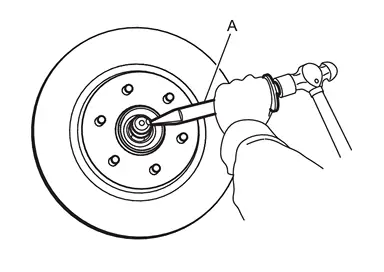 NOTE:
NOTE:
Use the following range for stacking the wheel hub lock nut
.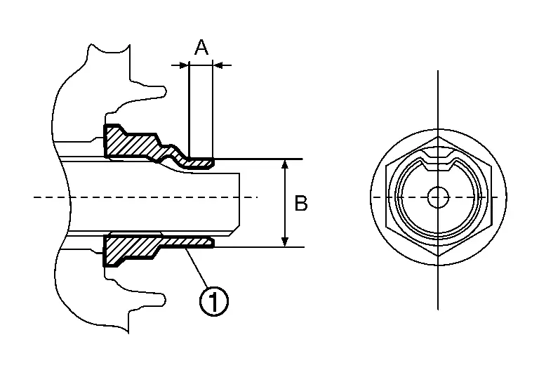
A : 6.2 mm (0.244 in) B : 29.4 - 30.8 mm (1.157 - 1.213 in)
Disassembly and Assembly
DISASSEMBLY
Fix shaft with a vise.
CAUTION:
Protect shaft when fixing with a vise using aluminum or copper plates.
Remove circular clip from housing.
Remove dust shield from housing.
Remove boot bands, and then remove boot from housing.
Put matching marks on housing and shaft.
CAUTION:
Use paint or similar substance for matching marks. Never scratch the surface.
Remove stopper ring with suitable tool, and pull out housing.
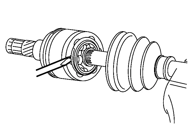
Put matching marks on ball cage/steel ball/inner race assembly and shaft.
CAUTION:
Use paint or similar substance for matching marks. Never scratch the surface.
Remove snap ring, then remove ball cage/steel ball/inner race assembly from shaft.
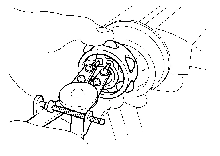
Remove boot from shaft.
Perform inspection after disassembly. Refer to Inspection.
ASSEMBLY
Remove old grease on housing with paper waste.
Install boot and boot bands to shaft.
CAUTION:
-
Wrap serration on shaft with tape
to protect the boot from damage.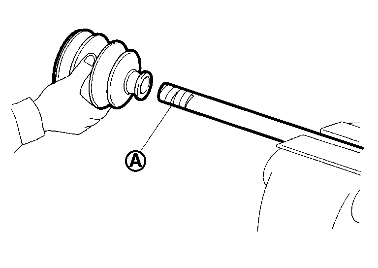
-
Never reuse boot and boot band.
Remove the tape wrapped around the serration on shaft.
Install ball cage/steel ball/inner race assembly , align it with the matching marks on shaft  put during the removal.
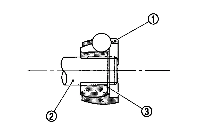
Secure ball cage/steel ball/inner race assembly onto shaft with snap ring  .
.
CAUTION:
Never reuse snap ring.
Apply the appropriate amount of grease onto housing and sliding surface.
| Grease amount | Drive Shaft |
Install housing to shaft.
Install stopper ring to housing.
CAUTION:
Never reuse stopper ring.
After installed, pull shaft to check engagement between housing and stopper ring.
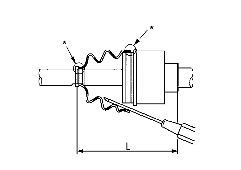
Install boot securely into grooves (indicated by “*” marks) shown in the figure.
CAUTION:
If grease adheres to the boot mounting surfaces (indicated by “*” marks) on shaft or housing, boot may be removed. Remove all grease from the surfaces.
To prevent deformation of the boot, adjust the boot installation length (L) to the value shown below by inserting the suitable tool into the inside of boot from the large diameter side of boot and discharging inside air.
| L | Drive Shaft |
CAUTION:
-
If the boot installation length is outside the standard, it may cause breakage of boot.
-
Be careful not to touch the inside of the boot with the tip of tool.
Secure the large and small ends of the boot with boot bands using the boot band crimping tool [SST: KV40107300 (NI-51751)] (A).
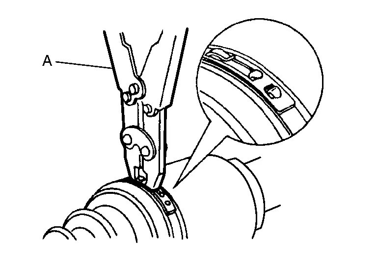
CAUTION:
Never reuse boot band.
NOTE:
Secure boot band so that dimension (M) meets the specification as shown in the figure.
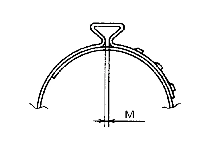
| M | : 1.0 – 4.0 mm (0.039 – 0.157 in) |
Secure housing and shaft, and then check that they are in the correct position when rotating boot. Install them with boot band when the mounting positions become incorrect.
CAUTION:
Never reuse boot band.
Install dust shield to housing.
CAUTION:
Never reuse dust shield.
Install circular clip to housing.
CAUTION:
Never reuse circular clip.
DISASSEMBLY
Fix shaft with a vise.
CAUTION:
Protect shaft when fixing with a vise using aluminum or copper plates.
Remove dust shield from joint sub-assembly.
Remove boot bands and then remove boot from joint sub-assembly.
Screw the drive shaft puller (commercial service tool) (A) 30 mm (1.18 in) or more into the thread of joint sub-assembly, and pull joint sub-assembly from shaft.
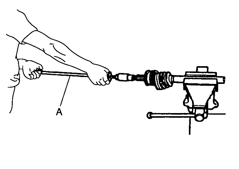
CAUTION:
-
If joint sub-assembly cannot be removed after five or more unsuccessful attempts, replace shaft and joint sub assembly as a set.
-
Align drive shaft puller and drive shaft and remove them by pulling directory.
Remove circular clip from shaft.
Remove boot from shaft.
Perform inspection after disassembly. Refer to Inspection.
ASSEMBLY
While rotating ball cage, clean old grease on joint sub-assembly with paper waste.
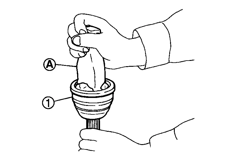
Fill serration slot joint sub-assembly with NISSAN genuine grease or equivalent until the serration slot and ball groove become full to the brim.
CAUTION:
After applying grease, use a shop cloth to wipe off old grease that has oozed out.
Install boot and boot bands to shaft.
CAUTION:
-
Wrap serration on shaft with tape
to protect the boot from damage. -
Never reuse boot and boot band.
Remove the tape wrapped around the serration on shaft.
Position circular clip on groove at the shaft edge.
CAUTION:
Never reuse circular clip.
NOTE:
Drive joint inserter is recommended when installing circular clip.
Align both center axles of the shaft edge and joint sub-assembly. Then assemble shaft with joint sub-assembly holding circular clip.
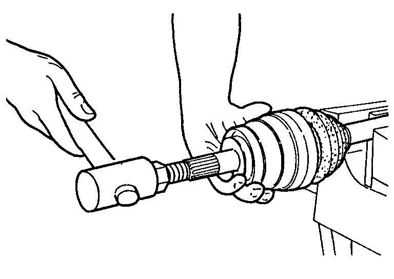
Install joint sub-assembly to shaft using plastic hammer.
WARNING:
Ensure that circular clip is properly engaged, otherwise the joint sub-assembly could pull away from transaxle during vehicle operation resulting in loss of drive force and possible drive shaft damage, which may cause a crash and serious injury or damage the drive shaft.
Pull the joint sub-assembly in the axial direction away from transaxle assembly. Confirm that the joint sub assembly cannot be pulled out.
Apply the specified amount of grease into the boot inside from large diameter side of boot.
| Grease amount | Drive Shaft |
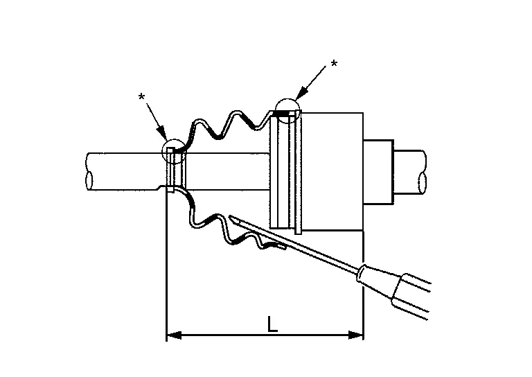
Install the boot securely into grooves (indicated by “*” marks) shown in the figure.
CAUTION:
If grease adheres to the boot mounting surface (indicated by “*” mark) on the shaft or housing, boot may come off. Remove all grease from the surfaces.
To prevent the deformation of the boot, adjust the boot installation length (L) to the specified value shown below by inserting the suitable tool into inside of the boot from the large diameter side of boot and discharging the inside air.
| L | Drive Shaft |
CAUTION:
-
If the boot installation length is outside the standard, it may cause breakage of boot.
-
Be careful not to touch the inside of the boot with the tip of tool.
Install new boot bands securely.
CAUTION:
Never reuse boot band.
Small boot band-
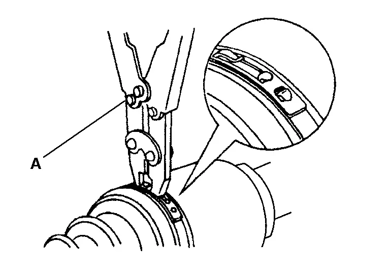
Secure the ends of the boot with boot bands using the boot band crimping tool [SST: KV40107300 (NI-51751)] (A).
CAUTION:
Secure boot band so that dimension (M) meets the specification as shown in the figure.
M : 1.0 – 4.0 mm (0.039 – 0.157 in)
CAUTION:
Never reuse boot band.
-
Set boot band to the drive shaft boot groove and temporarily fix pawl
of boot band to  of boot band.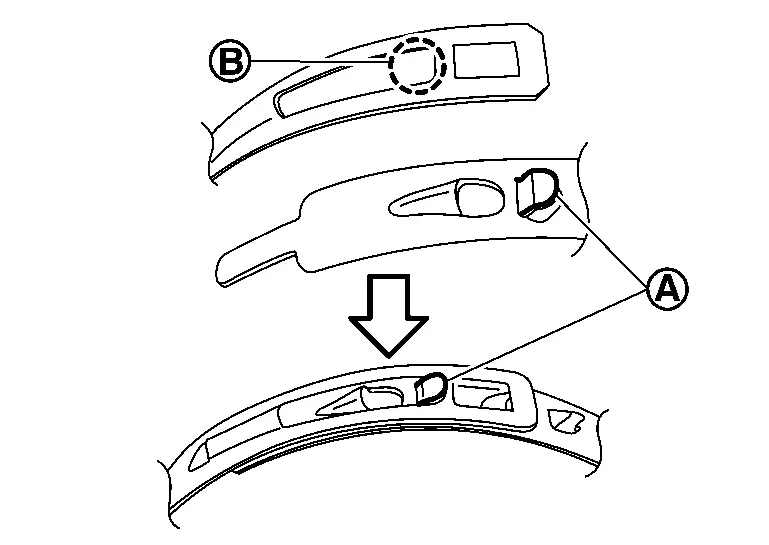
-
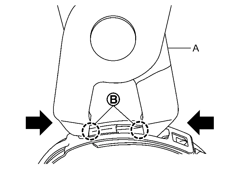
Pull protrusion of boot band tighten with boot band crimping tool [SST: KV40107310 (-)] (A) in the direction shown by arrows (
 ).
).
CAUTION:
Securely install boot band
to boot band pawl .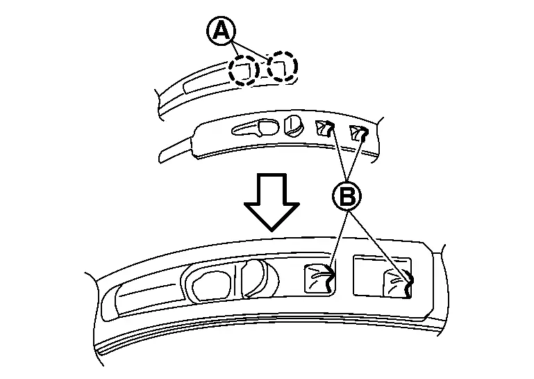
Secure joint sub-assembly and shaft, and then check that they are in the correct position when rotating boot. Install them with boot band when boot installation positions become incorrect.
CAUTION:
Never reuse boot band.
Install dust shield to joint sub-assembly.
CAUTION:
Never reuse dust shield.
Inspection
INSPECTION AFTER REMOVAL
-
Move joint up/down, left/right, and in the axial directions. Check for motion that is not smooth and for significant looseness.
-
Check boot for cracks, damage, and leakage of grease.
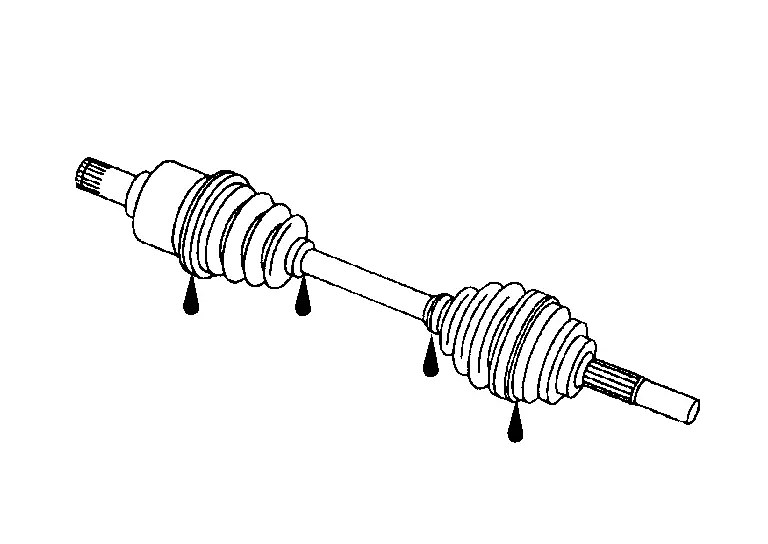
-
Disassemble drive shaft and exchange malfunctioning part if there is a non-standard condition.
INSPECTION AFTER DISASSEMBLY
Shaft
Check shaft for runout, cracks, or other damage. Replace it if necessary.
Joint Sub-Assembly (Wheel Side)
Check the following items, replace the parts if necessary.
-
Joint sub-assembly for rough rotation and excessive axial looseness.
-
The inside of the joint sub-assembly for entry of foreign material.
-
Joint sub-assembly for compression scars, cracks, and fractures inside of joint sub-assembly.
Replace joint sub-assembly if there are any non-standard conditions of components.
Housing (front final drive assembly side)
Replace housing if there is scratching or wear of housing roller contact surface.
INSPECTION AFTER INSTALLATION
Check wheel sensor harness for proper connection. Refer to Exploded View.
Check the wheel alignment. Refer to Inspection.
Adjust neutral position of steering angle sensor. Refer to Work Procedure.
Other materials
Radiator
Exploded View
Radiator drain cock
O-ring
Mounting rubber (upper)
Collar
Mounting rubber (lower)
Engine coolant temperature sensor 2
Radiator
Clamp
Radiator hose (lower)
Clamp
Reservoir tank tube
Reservoir tank bracket
Reservoir tank
Reservoir tank support ...
Precautions for Supplemental Restraint System (srs) Air Bag and Seat Belt Pre-Tensioner
PRECAUTIONS FOR SUPPLEMENTAL RESTRAINT SYSTEM (SRS) AIR BAG AND SEAT BELT PRE-TENSIONER : Precautions
The Supplemental Restraint System such as “AIR BAG” and “SEAT BELT PRE-TENSIONER”, used along with a front seat belt, helps to reduce the risk or severity of injury to the driver and front p ...
Rear Side Spoiler
Exploded View
Rear side spoiler
Double-sided tape
[t: 2.5 mm (0.098 in)]
: Clip
: Always replace after every disassembly.
Removal and Installation
REMOVALFully open back door.
Remove rear combination lamp cover. Refer to Removal and Installation.
Remove rear side spoile ...