Exploded View
WITHOUT DYNAMIC DIGITAL SUSPENSION AND ELECTRONIC AIR SUSPENSION
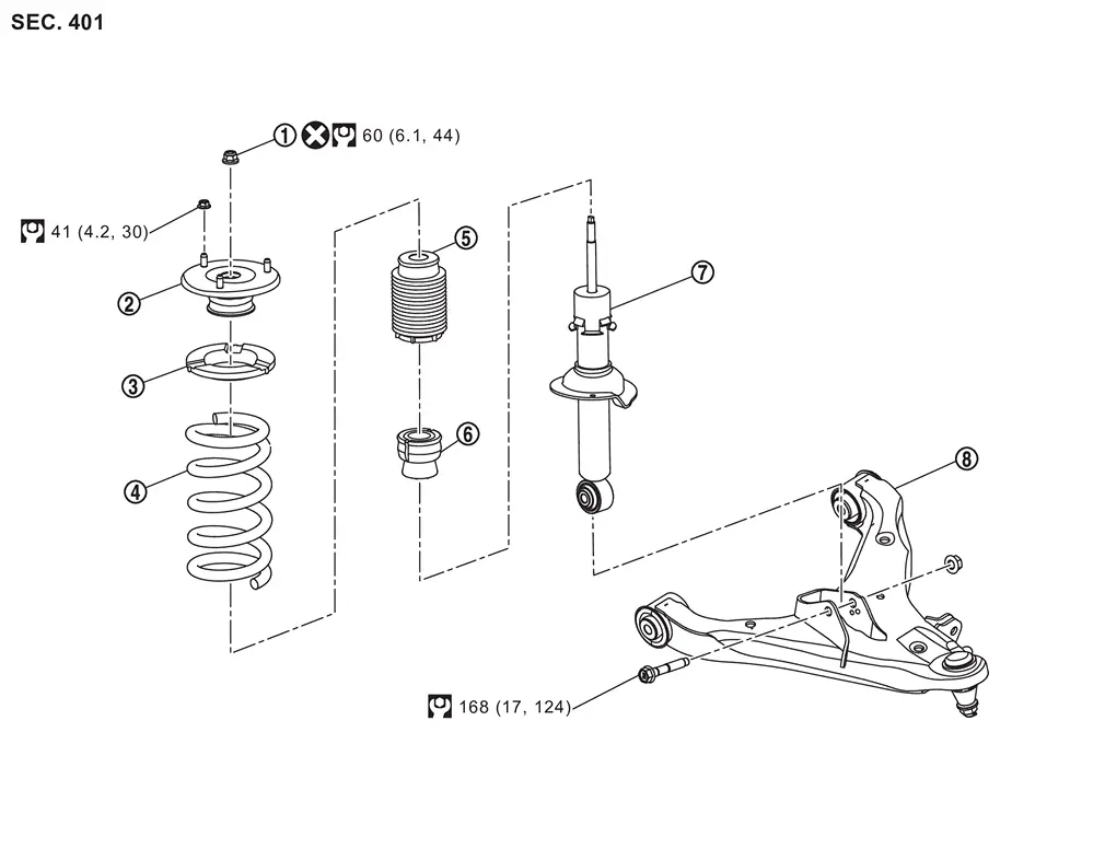
 |
Piston rod lock nut |  |
Mounting insulator |  |
Rubber seat |
 |
Coil spring |  |
Dust cover |  |
Bound bumper |
 |
Shock absorber |  |
Lower link | ||
 |
: Always replace after every disassembly. | ||||
 |
: N·m (kg-m, ft-lb) | ||||
WITH DYNAMIC DIGITAL SUSPENSION AND ELECTRONIC AIR SUSPENSION
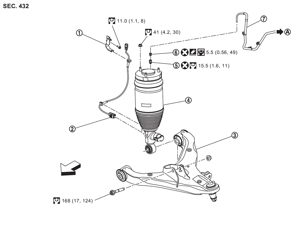
|
Bracket | |
Shock absorber harness | |
Lower link |
|
Shock absorber (With Built In Air Spring) | |
Air adapter | |
Air connector |
|
Air tube | ||||
 |
To air suspension control module | ||||
|
: Always replace after every disassembly. | ||||
 |
: Apply silicone sealant. | ||||
| : vehicle front | |||||
|
: N·m (kg-m, ft-lb) | ||||
 |
: N·m (kg-m, in-lb) |
CAUTION:
The shock absorber assembly cannot be disassembled.
Removal and Installation
REMOVAL
Without Dynamic Digital Suspension and Electronic Air Suspension
Remove tires. Refer to ROAD WHEEL TIRE : Removal & Installation.
Set suitable jack under lower link.
CAUTION:
Never damage lower link.
Remove brake hose bracket from steering knuckle. Refer to Removal and Installation.
Separate upper link from steering knuckle.
-
2WD models: Refer to Removal and Installation.
-
4WD models: Refer to Removal and Installation.
Remove shock absorber mounting nuts (upper side).
Remove shock absorber mounting bolt (lower side), and remove shock absorber from vehicle.
Perform inspection after removal. Refer to Inspection.
With Dynamic Digital Suspension and Electronic Air Suspension
WARNING:
-
When checking under the vehicle or inside wheel house, always turn OFF the electronic air suspension function with the vehicle unladen and normal height, since the suspension may accidentally move and it can lead to personal injury. Refer to the operation procedures on the reference to set normal height and turn off the system functions. Refer to Precaution for Electronic Air Suspension System.
-
When removing the air suspension component parts, always follow the removing procedure since the vehicle height may accidentally drop and it can lead to personal injury.
CAUTION:
-
Never grab and deform the boots
of the air spring when remove and installing. If deformed, return it without stretching.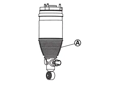
Start engine.
Turn auto height mode control switch to ON, shift the shift position to N and set to normal height.
Turn OFF the electronic air suspension function. Refer to Operation.
Stop engine.
Lift up the vehicle.
Remove tires. Refer to ROAD WHEEL TIRE : Removal & Installation.
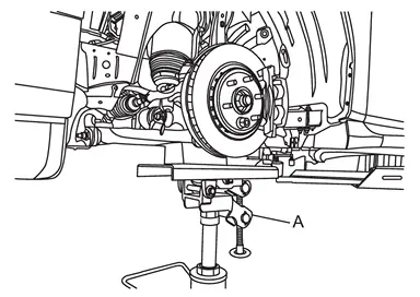
Set suitable jack (A) under lower link.
CAUTION:
Never damage lower link.
Disconnect shock absorber harness connector , and remove shock absorber harness and bracket from vehicle.
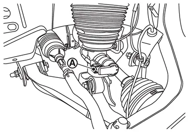
Remove silicone sealant between the air connector  and air adapter
  .
.
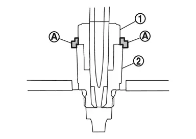
CAUTION:
Never damage air connector and air adapter.
Apply the matching marks to the air tube when replacing air connector .
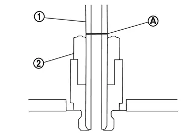
Loosen the air connector and perform air bleeding.
CAUTION:
-
Be careful since air flows swiftly from air tube.
-
Loosen the air connector slowly.
-
Never disconnect the air connector until the air completely bleeds.
-
Never damage air connector.
When reusing the air connector, remove air tube together with air connector from air adapter  .
.
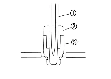
CAUTION:
-
Never damage air connector, air adapter, and air tube.
-
When reusing air connector, never remove air tube from air connector.
-
If you remove the air tube from the air connector, be sure to replace the air connector.
-
Seal remove part using vinyl tape for preventing dirt from getting the remove part.
 NOTE:
NOTE:
The air connector can be reused as long as you never remove air tube from air connector.
When replacing the air connector, follow the procedure below.Slide the air connector part to direction  , and remove the part
  from the air tube .
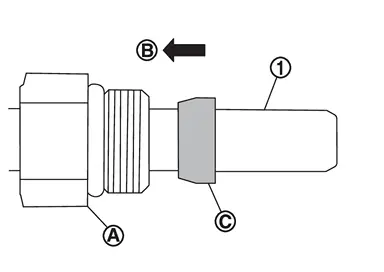
CAUTION:
Never damage air connector and air tube.
Remove the air connector part from the air tube .
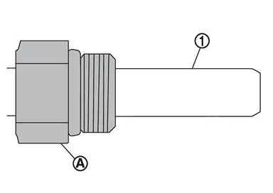
CAUTION:
Never damage air connector and air tube.
Remove air adapter from shock absorber if necessary.
CAUTION:
Seal remove part using vinyl tape for preventing dirt from getting the remove part.
Remove brake hose bracket from steering knuckle. Refer to Removal and Installation.
Separate upper link from steering knuckle.
-
2WD: Refer to Removal and Installation.
-
4WD: Refer to Removal and Installation.
Remove shock absorber mounting nuts (upper side).
Remove shock absorber mounting bolt (lower side), and remove shock absorber from vehicle.
Perform inspection after removal. Refer to Inspection.
INSTALLATION
Without Dynamic Digital Suspension and Electronic Air Suspension
Note the following, and install in the reverse order of removal.
-
Perform final tighting of shock absorber (lower side) by the following procedures.
-
Measure between wheel center and fender arch (A).
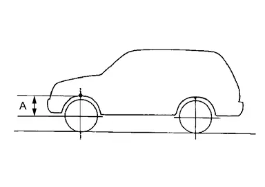 NOTE:
NOTE:
Note the measurements.
-
Set the wheel chocks on the rear tires.
-
Jack up front of the vehicle and set the rigid rack.
-
Remove the front tires.
-
Set suitable jack (A) on the left and right steering knuckles
(lower link ball joint fastening part). 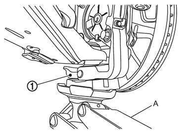
CAUTION:
Never damage threaded part of ball joint.
-
Jack up the left and right steering knuckles until the vehicle no longer floats off the rigid rack (A).
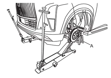
CAUTION:
-
Never damage steering knuckles.
-
Check the stable condition when using a suitable jack.
-
Never float the vehicle.
NOTE:
Jack up left and right at the same time.
-
-
Measure between wheel center and fender arch (A).
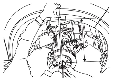
CAUTION:
-
Check the measurements are within +20 mm (0.79 in) from step 1.
-
If the measurements are +20 mm (0.79 in) or more, perform step 6 again.
-
-
Tight the mounting bolt of shock absorber (lower side) to the specified torque. Refer to Exploded View.
-
-
Perform inspection after installation. Refer to Inspection.
-
Perform adjustment after installation. Refer to Adjustment.
-
After replacing the shock absorber, always follow the disposal procedure to discard the shock absorber. Refer to Disposal.
With Dynamic Digital Suspension and Electronic Air Suspension
Install shock absorber to vehicle.
Install shock absorber harness connector, shock absorber harness, and bracket.
CAUTION:
Never twist or pull shock absorber harness, when installing.
Install upper link to steering knuckle.
-
2WD: Refer to Removal and Installation.
-
4WD: Refer to Removal and Installation.
Install brake hose bracket to steering knuckle. Refer to Removal and Installation.
Install air adapter to shock absorber if necessary.
CAUTION:
Never let foreign materials entered into parts.
When reusing the air connector, install air tube and air connector together to air adapter .
CAUTION:
-
Never damage air connector, air adapter, and air tube.
-
If you remove the air tube from the air connector, be sure to replace the air connector.
-
Never let foreign materials entered into parts.
When replacing the air connector, follow the procedure below.Install air connector to air adapter .
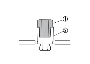
CAUTION:
-
Never damage air connector and air adapter.
-
Never reuse air connector.
-
Never remove the air connector cover until air tube is installed.
-
Never let foreign materials entered into parts.
straight into the air connector to the marked point which is applied when removing.
CAUTION:
-
Securely insert the air tube with no damage and twist.
-
Never remove the air connector cover until air tube is installed.
-
Never let foreign materials entered into parts.
Apply silicone sealant to faces air connector and air adapter .
CAUTION:
-
Before applying the silicone sealant, make sure that there are no clearance between air adapter and air connector.
-
Apply the silicone sealant to the air adapter and air connector jointed parts without any clearance.
Start engine.
Use CONSULT and fill the inner pressure of shock absorber to 5.7 bar. Refer to Work Support.
Stop engine.
Install tire. Refer to ROAD WHEEL TIRE : Exploded View.
Lift down the vehicle.
Start engine.
Perform pressure measurements using CONSULT. Refer to Work Support.
NOTE:
Confirm that "Air suspension internal pressure judgement" is OK.
Use CONSULT and vehicle to the normal height. Refer to Work Support.
Turn ON the electronic air suspension function. Refer to Operation.
Stop engine.
Perform final tighting of shock absorber (lower side) by the following procedures.Measure between wheel center and fender arch (A).
NOTE:
Note the measurements.
Set the wheel chocks on the rear tires. Jack up front of the vehicle and set the rigid rack. Remove the front tires. Set suitable jack (A) on the left and right steering knuckles (lower link ball joint fastening part).
CAUTION:
Never damage threaded part of ball joint.
Jack up the left and right steering knuckles until the vehicle no longer floats off the rigid rack (A).
CAUTION:
-
Never damage steering knuckles.
-
Check the stable condition when using a suitable jack.
-
Never float the vehicle.
NOTE:
Jack up left and right at the same time.
Measure between wheel center and fender arch (A).
CAUTION:
-
Check the measurements are within +20 mm (0.79 in) from step a.
-
If the measurements are +20 mm (0.79 in) or more, perform step f again.
Perform inspection after installation. Refer to Inspection.
Perform adjustment after installation. Refer to Adjustment.
After replacing the shock absorber, always follow the disposal procedure to discard the shock absorber. Refer to Disposal.
Disassembly & Assembly
DISASSEMBLY
Without Dynamic Digital Suspension and Electronic Air Suspension
CAUTION:
Never damage shock absorber piston rod when removing components from shock absorber.
Install shock absorber attachment [SST: ST35652000 ( − )] (A) to shock absorber and secure it in a vise.
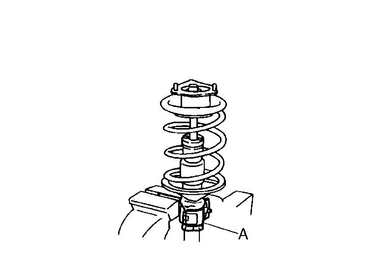
CAUTION:
When installing the shock absorber attachment to shock absorber, wrap a shop cloth around shock absorber to protect it from damage.
Using a spring compressor (commercial service tool) (A), compress coil spring between rubber seat and shock absorber until coil spring with a spring compressor is free.
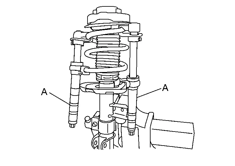
CAUTION:
Be sure the spring compressor is securely attached to coil spring, before compressing it.
Check coil spring with a spring compressor between rubber seat and shock absorber is free. Remove piston rod lock nut while securing the piston rod tip so that piston rod does not turn.
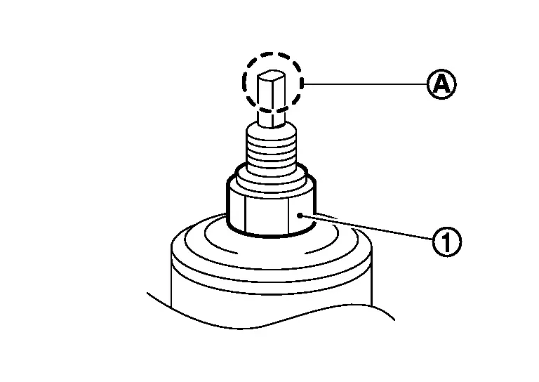
Remove mounting insulator, rubber seat, dust cover, and bound bumper from shock absorber.
After removing coil spring with spring compressor (commercial service tool), gradually release the spring compressor.
CAUTION:
Loosen while making sure coil spring attachment position does not move.
Remove the shock absorber attachment [SST: ST35652000 ( − )] from shock absorber.
Perform inspection after disassembly. Refer to Inspection.
With Dynamic Digital Suspension and Electronic Air Suspension
CAUTION:
The shock absorber assembly cannot be disassembled.
ASSEMBLY
Without Dynamic Digital Suspension and Electronic Air Suspension
Install bound bumper to dust cover .
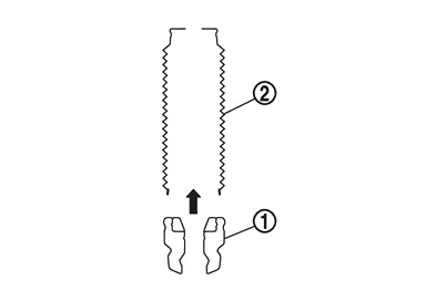
Install dust cover and bound bumper to mounting insulator .
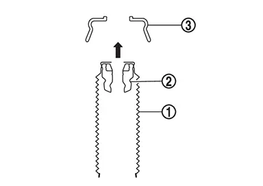
Install shock absorber to bound bumper, dust cover, and mounting insulator.
NOTE:
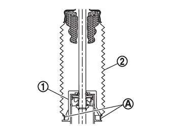
Check that part of dust cover is attached to shock absorber .
Install shock absorber attachment [SST: ST35652000 ( − )] to shock absorber and secure it in a vise.
CAUTION:
When installing the shock absorber attachment to shock absorber, wrap a shop cloth around shock absorber to protect it from damage.
Compress coil spring using a spring compressor (commercial service tool), and install it onto shock absorber.
CAUTION:
-
Be sure the spring compressor is securely attached to coil spring, before compressing it.
-
Set coil spring so that its paint marks
are aligned with the position from the bottom end of the coil spring as shown in the figure.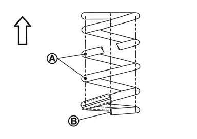

: Upper side : Lower end of the coil spring shall be at vehicle out side
Align and attach the protrusions of the rubber sheet to the bolts of the mounting insulator .
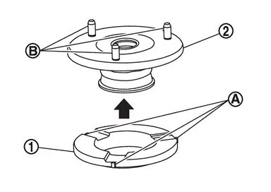
Install rubber sheet and mounting insulator to shock absorber.
-
Install the mounting insulator
as shown in the figure.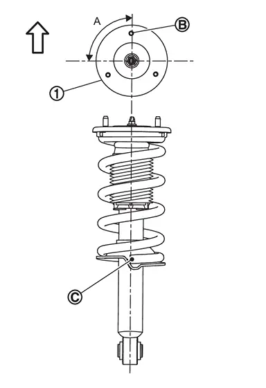
Angle (A) : 90° : mounting insulator bolt : lower end of the coil spring -
Align the lower end of the coil spring
with the position (A) of the shock absorber in the diagram.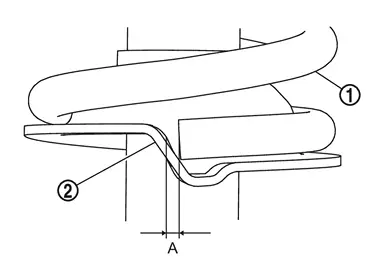
A : 5 mm or less
Secure piston rod tip so that piston rod does not turn, then tighten piston rod lock nut to the specified torque.
Gradually release a spring compressor (commercial service tool), and remove coil spring.
CAUTION:
Loosen while making sure coil spring attachment position does not move.
Remove the shock absorber attachment [SST: ST35652000 ( − )] from shock absorber.
Inspection
WITHOUT DYNAMIC DIGITAL SUSPENSION AND ELECTRONIC AIR SUSPENSION
Inspection After Removal
Check shock absorber for oil leakage or other malfunctions. Replace it if necessary.
Inspection After Installation
Check wheel alignment. Refer to Inspection.
WITH DYNAMIC DIGITAL SUSPENSION AND ELECTRONIC AIR SUSPENSION
Inspection After Removal
Check shock absorber for oil leakage or other malfunctions. Replace it if necessary.
Inspection After Installation
-
Make sure the electronic air suspension function is turn ON. Refer to Operation.
-
Confirm that no warning message is displayed on the information display. Refer to Air suspension warning.
-
Perform the self-diagnosis with CONSULT. Check if any DTC is detected. Refer to CONSULT Function.
-
Confirm to close the hood.
-
Always check for the air leakage with soapy water.
-
Check wheel alignment. Refer to Inspection.
Adjustment
WITHOUT DYNAMIC DIGITAL SUSPENSION AND ELECTRONIC AIR SUSPENSION
Adjustment After Installation
Adjust neutral position of steering angle sensor. Refer to Work Procedure.
WITH DYNAMIC DIGITAL SUSPENSION AND ELECTRONIC AIR SUSPENSION
Adjustment After Installation
Adjust neutral position of steering angle sensor. Refer to Work Procedure.
Disposal
-
Set shock absorber horizontally with the piston rod fully extended.
-
Drill 2 – 3 mm (0.08 – 0.12 in) hole at the position (
 ) from top as shown in the figure to release gas gradually.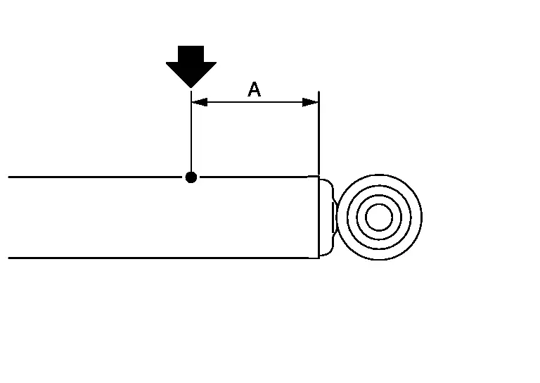
CAUTION:
-
Wear eye protection (safety glasses).
-
Wear gloves.
-
Be careful with metal chips or oil blown out by the compressed gas.
NOTE:
-
Drill vertically in this direction (
 ).
). -
Directly to the outer tube avoiding brackets.
-
The gas is clear, colorless, odorless, and harmless.
A : 20 – 30 mm (0.79 – 1.18 in) -
-
Position the drilled hole downward and drain oil by moving the piston rod several times.
CAUTION:
Dispose of drained oil according to the law and local regulations.
Other materials
Electric Power Steering Warning Lamp Does Not Turn on
Description
The power steering warning lamp does not illuminate when the ignition switch is ON (lamp check).
Diagnosis Procedure
CHECK THE POWER STEERING WARNING LAMP
Perform trouble diagnosis for the power steering warning lamp system. Refer to Component Function Check.
Is the inspection result nor ...
Third Seat
Removal and Installation
REMOVALFolding the seatback of third seat.
NOTE:
If seatback of third seat cannot be folded, access the third seat control unit from the front side of third seat.
Remove third seat control unit fixing screws and then remove third seat control unit.
Disconnect third seat c ...
Normal Operating Condition
Symptom Table
NOTE:
For Navigation system operation information, refer to Navigation system Owner's Manual.BASIC OPERATIONS Symptom Possible cause Possible solution
No image is displayed.
The brightness is at the lowest setting.
Adjust the brightness of the display.
The systems in the vid ...