Removal and Installation
CAUTION:
-
Perform work with 2 workers, because it is heavy weight.
-
Support hood with a proper material and use protective tape or shop cloth to protect hood and body from falling and damage when removing and installing hood assembly.
REMOVAL
Support hood assembly with a proper material to prevent it from falling.
WARNING:
Injury may occur if hood assembly is not supported with a proper material when removing hood assembly.
Remove hood assembly mounting nuts, and then remove hood assembly.
INSTALLATION
Note the following items, and then install in the reverse order of removal.
CAUTION:
-
Before installation, apply anticorrosive agent onto mounting surface.
-
When installation, perform the fitting adjustment. Refer to Adjustment.
-
After installation, apply touch-up paint (the body color) if the paint around hinge is peeled off during removal.
-
After installation, check the open/close operation. Refer to Inspection.
Inspection
Open and close hood. Check that hood hinge rotation portion moves smoothly.
Check hood hinge rotating part for lubrication condition. If necessary, apply grease.
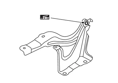
 |
: Body grease |
Adjustment
FITTING ADJUSTMENT
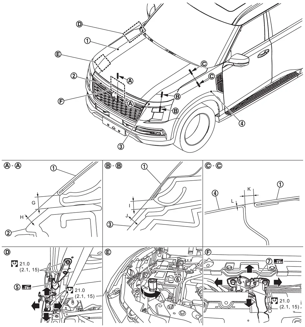
Fitting Adjustment Standard Dimension
 |
Hood assembly |  |
Front grille |  |
Front combination lamp |
 |
Front fender assembly |  |
Hood hinge |  |
Hood bumper rubber 1 |
 |
Hood lock assembly | ||||
 |
: N·m (kg-m, ft-lb) | ||||
|
: Body grease | ||||
Unit: mm [in]
| Portion | Standard | Tolerance |
Difference (RH/LH, MAX) | |||
|---|---|---|---|---|---|---|
| Hood assembly – Front grille |  – – |
G | Clearance |
5.0 [0.197] |
± 2.6 [± 0.102] |
— |
| H | Surface height |
2.0 – 2.7 [0.079 – 0.106] |
± 2.4 [± 0.094] |
— | ||
| Hood assembly – Front combination lamp |  – – |
I | Clearance |
4.7 – 5.1 [0.185 – 0.201] |
± 2.6 [± 0.102] |
< 2.0 [0.079] |
| J | Surface height |
1.9 – 2.4 [0.075 – 0.094] |
± 2.3 [± 0.091] |
< 2.1 [0.083] | ||
| Hood assembly – Front fender assembly |  – – |
K | Clearance |
4.5 [0.177] |
± 1.5 [± 0.059] |
< 2.0 [0.079] |
| L | Surface height |
0.0 [0.000] |
± 1.0 [± 0.039] |
< 2.0 [0.079] | ||
Check the clearance and the surface height between hood assembly and each part by visually and touching.
If the clearance and the surface height are out of specification, adjust them according to the procedures shown below.
Fitting Adjustment Procedure
Remove hood lock assembly. Refer to Removal and Installation.
Adjust the surface height of hood assembly according to the fitting adjustment standard dimension by rotating hood bumper rubber 1.
Remove front fender assembly. Refer to Removal and Installation.
Loosen hood hinge mounting bolts.
Temporary install front fender assembly, front combination lamp and front grille, and then adjustment clearance of hood assembly according to the specified value by moving hood assembly.
Remove temporary installed parts, and then tighten hood hinge mounting bolts to the specified torque.
CAUTION:
After tightening, apply touch-up paint (the body color) if the paint around hinge and mounting bolts are peeled off during adjustment.
Install front fender assembly. Refer to Removal and Installation.
Install front combination lamp. Refer to Removal and Installation.
Install front grille. Refer to Removal and Installation (OFF ROAD MODELS) or Removal and Installation (CITY MODELS).
Install hood lock assembly and temporary tighten hood lock assembly mounting bolts, and then position hood lock assembly and engage hood striker. Check hood lock assembly and hood striker for looseness. Refer to Removal and Installation.
Move hood lock assembly laterally until the center of hood striker and hood lock assembly are vertical when viewed from the front.
Tighten hood lock assembly mounting bolts to the specified torque.
Install front grille upper. Refer to Removal and Installation (OFF ROAD MODELS) or Removal and Installation (CITY MODELS).
CAUTION:
-
After adjusting, check the open/close operation. Refer to Inspection.
-
After installation, perform hood lock control inspection. Refer to Inspection.
Other materials
Touch screen display
Basic information
In the Nissan Armada, many vehicle systems and advanced features can be conveniently
controlled through the intuitive touch screen display, providing a modern and user-friendly
interface for drivers.
For a complete overview of touch screen operation in the Nissan Armada, refe ...
Emission control system warranty
Your Nissan Armada is protected by comprehensive emission-related warranties
designed to ensure compliance with environmental regulations and maintain optimal
engine performance.
For USA:
Emission Defects Warranty – Covers defects in materials or workmanship that
may affect emissions s ...
Intelligent Rear View Mirror System Does Not Operate
Diagnosis Procedure
INTELLIGENT REAR VIEW MIRROR FUNCTIONAL INSPECTION
Ignition switch ON.
Check the intelligent rear view mirror system is operating normally after setting power supply lever of intelligent rear view mirror lower part to ON.
Is the inspection result normal?
YES>>
GO TO ...