Exploded View
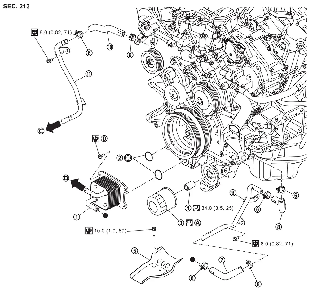
 |
Oil cooler |  |
O-ring |  |
Oil filter |
 |
Connector bolt |  |
Oil catch plate |  |
Clamp |
 |
Oil cooler hose 2 |  |
Oil cooler hose 3 |  |
Oil cooler pipe 2 |
 |
Oil cooler hose 1 |  |
Oil cooler pipe 1 | ||
 |
Comply with the installation procedure when tightening. Refer to Removal and Installation |  |
To A/T water hose A. Refer to Exploded View |  |
To A/T water hose B. Refer to Exploded View |
 |
Comply with the installation procedure when tightening. Refer to Removal and Installation | ||||
 |
: N·m (kg-m, ft-lb) | ||||
 |
: N·m (kg-m, in-lb) | ||||
 |
: Always replace after every disassembly. | ||||
 : Indicates that the part is connected at points with same symbol in actual vehicle. : Indicates that the part is connected at points with same symbol in actual vehicle. |
|||||
Removal and Installation
WARNING:
-
Jacking up or lift up the vehicle may the vehicle height to go down which cause a personal injury and/or damage to the air suspension component parts. Refer to Precaution for when Jacking and Lifting Up the vehicle with Electronic Air Suspension System.
REMOVAL
WARNING:
Never get burn yourself, as engine oil and engine coolant may be hot.
Remove engine under cover, using a power tool (commercial service tool). Refer to Removal and Installation.
Drain engine oil. Refer to Draining.
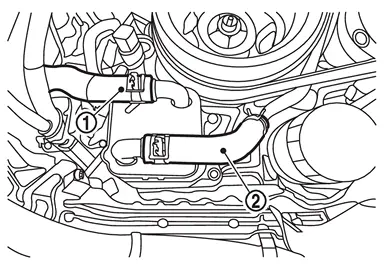
Disconnect A/T fluid cooler hose and oil cooler hose 2 .
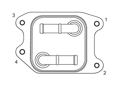
Loosen oil cooler mounting bolts in the reverse order of the figure and remove the oil cooler.
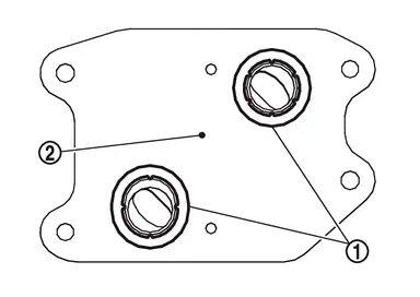
Remove O-ring from oil cooler .
INSTALLATION
Note the following, and install in the reverse order of removal.
CAUTION:
Do not reuse O-ring.
Tighten oil cooler mounting bolts to the specified torque in the order shown in the figure.
| : 10.0 N·m (1.0 kg-m, 89 in-lb) |
Inspection
WARNING:
-
Jacking up or lift up the vehicle may the vehicle height to go down which cause a personal injury and/or damage to the air suspension component parts. Refer to Precaution for when Jacking and Lifting Up the vehicle with Electronic Air Suspension System.
INSPECTION AFTER REMOVAL
Oil Cooler
Check oil cooler for cracks. Check oil cooler for clogging by blowing through engine coolant inlet. If necessary, replace oil cooler.
Relief Valve
Check relief valve with the following procedure.
-
Press steel ball of relief valve using a clean plastic stick. Check that valve moves smoothly and proper spring repulsion is felt.
-
Replace relief valve, if necessary, with the following procedure.
-
Remove the relief valve by prying using a screwdriver.
CAUTION:
Never damage the mounting hole.
-
Press in the relief valve until it reaches a depth of 7 mm (0.28 in) from end surface of oil pan (upper) using approximately 10 mm (0.39 in) diameter drift.
CAUTION:
Carefully press in the relief valve by aligning its mounting hole side with the axle center so as not to cause deformation.
-
INSPECTION AFTER INSTALLATION
Check the engine oil level and the engine coolant level and add engine oil and engine coolant. Refer to ENGINE COOLANT : Inspection and refer to Inspection.
Start the engine, and check there is no leakage of engine oil or engine coolant.
Stop the engine and wait for 10 minutes.
Check the engine oil level and the engine coolant level again. Refer to ENGINE COOLANT : Inspection and refer to Inspection.
Other materials
Precautions
PRECAUTIONS FOR SUPPLEMENTAL RESTRAINT SYSTEM (SRS) AIR BAG AND SEAT BELT PRE-TENSIONER : Precautions
The Supplemental Restraint System such as “AIR BAG” and “SEAT BELT PRE-TENSIONER”, used along with a front seat belt, helps to reduce the risk or severity of injury to the driver and front p ...
Passenger Door Mirror Control Module
Exploded View
Passenger door mirror control module
Clip
Front door panel
: vehicle front
Removal and Installation
REMOVALRemove front door finisher (passenger side). Refer to Removal & Installation.
Disconnect harness connector.
Disengage passenger door mirror control module fixin ...
Front Washer Nozzle
Removal and Installation
REMOVALCAUTION:
When washer tube is disconnected/removed, washer fluid may come out so prepare a container to receive washer fluid and never allow washer fluid to be sprinkled.Remove cowl top cover. Refer to Removal and Installation.
Remove front washer nozzle tube LH and RH ...