
Nissan Armada 2025-2026 Service and Repair Manual: Removal and Installation
WARNING:
WITHOUT DYNAMIC DIGITAL SUSPENSION AND ELECTRONIC AIR SUSPENSION
Removal
Remove tires. Refer to ROAD WHEEL TIRE : Removal & Installation.
Remove brake hose bracket from suspension arm. Refer to Removal and Installation.
Remove caliper assembly. Hang caliper assembly in a place where it will not interfere with work. Refer to Removal and Installation.
CAUTION:
Never depress brake pedal while caliper assembly is removed.
Remove disc rotor.
CAUTION:
Put matching marks
 on the wheel hub and bearing assembly and the disc rotor before removing the disc rotor.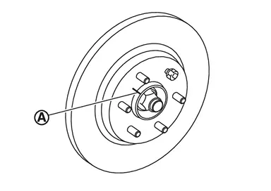
Never drop disc rotor.
Remove wheel sensor harness. Refer to Removal and Installation.
Put matching mark on drive shaft and wheel hub and bearing assembly.
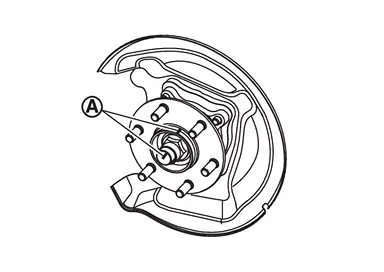
CAUTION:
Use paint or similar substance for matching marks. Never scratch the surface.
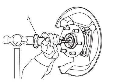
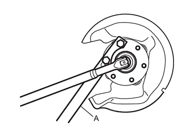
Using lock nut chisel [SST: KV40108800 ( − )] (A), release stacked area of wheel hub lock nut.
CAUTION:
Completely release the caulking part of the wheel hub lock nut.
Never add damage to the driveshaft side screw thread with wheel hub lock nut.
 NOTE:
NOTE:
CAUTION:
Never use a power tool.
Set suitable jack under rear lower link.
Remove rear lower link and coil spring. Refer to Removal and Installation.
Using jack to front lower link.
Loosen the front lower link frame side bolt.
Remove cotter pin and nut, and remove front lower link from axle housing.
Remove cotter pin and nut, and remove suspension arm from axle housing.
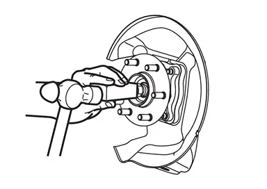
Patch wheel hub lock nut with a piece of wood. Hammer the wood to disengage wheel hub and bearing assembly from drive shaft. Take out the wheel hub lock nut.
CAUTION:
Never place drive shaft joint at an extreme angle. Also be careful not to overextend slide joint.
Never allow drive shaft to hang down without support for counterpart such as joint sub-assembly, and other parts.
NOTE:
Use a suitable puller, if the wheel hub and bearing assembly and drive shaft cannot be separated even after performing the above procedure.
Remove wheel hub and bearing assembly.
Remove axle housing.
Remove back plate from axle housing.
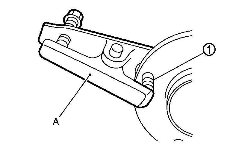
Remove hub bolts  from wheel hub and bearing assembly, using the ball joint remover (commercial service tool) (A).
CAUTION:
Remove hub bolt only when necessary.
Never hammer the hub bolt to avoid impact to the wheel hub and bearing assembly.
Pull out the hub bolt in a direction perpendicular to the wheel hub and bearing assembly.
Perform inspection after removal. Refer to Inspection.
Installation
Note the following, and install in the reverse order of removal.
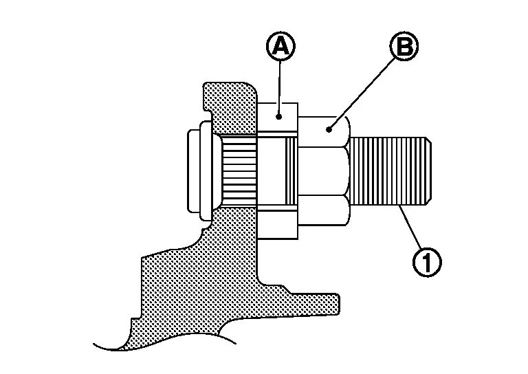
Place a washer
as shown in the figure to install the hub bolts by using the tightening force of the nut  .
.
CAUTION:
Check that there is no clearance between wheel hub and bearing assembly, and hub bolt.
Never reuse hub bolt.
CAUTION:
Never apply lubricating oil to these matching surface.
CAUTION:
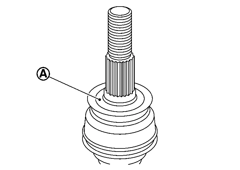
Apply paste to cover entire flat surface of joint sub-assembly of drive shaft.
Amount paste 1.0 – 3.0 g (0.04 – 0.10 oz) When installing drive shaft to wheel hub, never align drive shaft staked area
and one of hub bolts .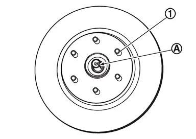
Use the following torque range for tightening the wheel hub lock nut.

: 218 – 223 N·m (22 – 23 kg-m, 161 – 164 ft-lb) CAUTION:
Never reuse wheel hub lock nut.
NOTE: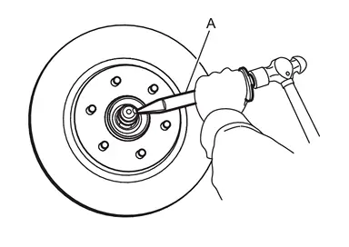 NOTE:
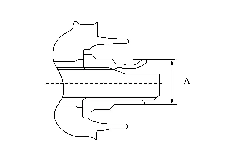
NOTE:Use the following range for stacking the whell hub lock nut.
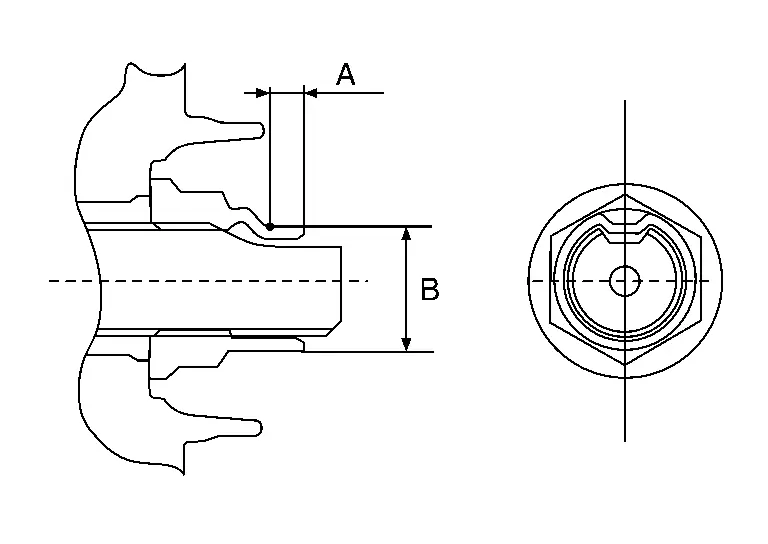
A : 6.2 mm (0.244 in) B : 29.4 – 30.8 mm (1.157 – 1.213 in) Perform the final tightening of each of parts under unladen conditions, which were removed when removing wheel hub and bearing assembly and axle housing.
Perform inspection after installation. Refer to Inspection.
WITH DYNAMIC DIGITAL SUSPENSION AND ELECTRONIC AIR SUSPENSION
Removal
Start engine.
Turn OFF the electronic air suspension function. Refer to Operation.
Stop engine.
Lift up the vehicle.
Remove rear tire. Refer to ROAD WHEEL TIRE : Removal & Installation.
CAUTION:
Never depress brake pedal while caliper assembly is removed.
Remove disc rotor.
CAUTION:
Never drop disc rotor.
Remove wheel sensor harness. Refer to Removal and Installation.
Put matching mark on drive shaft and wheel hub and bearing assembly.
CAUTION:
Use paint or similar substance for matching marks. Never scratch the surface.
CAUTION:
Completely release the caulking part of the wheel hub lock nut.
Never add damage to the driveshaft side screw thread with wheel hub lock nut.
NOTE:
CAUTION:
Never use a power tool.
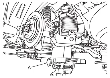
Support the rear lower link with suitable jack (A) until most horizontal angle with vehicle on the ground.
CAUTION:
Never damage rear lower link.
Check the stable condition when using a suitable jack.
Never lower the suitable jack until installation is completed.
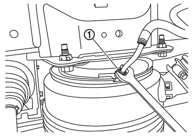
Loosen the air connector and perform air bleeding.
CAUTION:
Be careful since air flows swiftly from air tube.
Loosen the air connector slowly.
Never disconnect the air connector until the air completely bleeds.
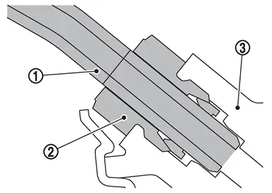
Remove air tube together with air connector  from air spring
  .
.
CAUTION:
Never damage air connector, air adapter, and air tube.
When reusing air connector, never remove air tube from air connector.
If you remove the air tube from the air connector, be sure to replace the air connector.
Seal remove part using vinyl tape for preventing dirt from getting the remove part.
NOTE:
The air connector can be reused as long as you never remove air tube from air connector.
Loosen rear lower link mounting nuts (frame side). Refer to Removal and Installation.
Remove rear lower link from axle housing. Refer to Removal and Installation.
Using jack to front lower link.
Loosen the front lower link frame side bolt.
Remove cotter pin and nut, and remove front lower link from axle housing.
Remove cotter pin and nut, and remove suspension arm from axle housing.
CAUTION:
NOTE:
- NOTE:
Remove wheel hub and bearing assembly.
Remove axle housing.
Remove back plate from axle housing.
Remove hub bolt from wheel hub and bearing assembly, using the ball joint remover (commercial service tool) (A).
CAUTION:
Remove hub bolt only when necessary.
Never hammer the hub bolt to avoid impact to the wheel hub and bearing assembly.
Pull out the hub bolt in a direction perpendicular to the wheel hub and bearing assembly.
Perform inspection after removal. Refer to Inspection.
Installation
Place a washer as shown in the figure to install the hub bolts by using the tightening force of the nut .
CAUTION:
Check that there is no clearance between wheel hub and bearing assembly, and hub bolt.
Never reuse hub bolt.
Install back plate to axle housing.
Install axle housing.
Install wheel hub and bearing assembly, follow the note below.
- Clean the matching surface of wheel hub lock nut and wheel hub and bearing assembly.
CAUTION:
Never apply lubricating oil to these matching surface.
CAUTION:
Apply paste to cover entire flat surface of joint sub-as- sembly of drive shaft.
Amount paste 1.0 – 3.0 g (0.04 – 0.10 oz) When installing drive shaft to wheel hub and bearing assembly, never align drive shaft staked area
and one of hub bolts . CAUTION:
Align the matching marks made during removal when reusing the wheel hub and bearing assembly.
Install cotter pin and nut, and install suspension arm to axle housing.
Install cotter pin and nut, and install front lower link to axle housing.
Tighten front lower link mounting nuts (frame side).
Install rear lower link to axle housing. Refer to Removal and Installation.
Tighten rear lower link mounting nuts (frame side). Refer to Removal and Installation.
Install wheel hub lock nut, follow the note below.
Use the following torque range for tightening the wheel hub lock nut.
: 218 – 223 N·m (22 – 23 kg-m, 161 – 164 ft-lb) CAUTION:
Never reuse wheel hub lock nut.
NOTE:- NOTE:
Use the following range for stacking the whell hub lock nut.
A : 6.2 mm (0.244 in) B : 29.4 – 30.8 mm (1.157 – 1.213 in)
Install wheel sensor harness. Refer to Removal and Installation.
Install disc rotor.
CAUTION:
Align the matching marks made during removal when reusing the disc rotor.
Install brake caliper assembly. Refer to Removal and Installation.
Install brake hose bracket to suspension arm. Refer to Removal and Installation.
Install air tube and air connector together to air spring .
CAUTION:
Never damage air connector and air tube.
Never let foreign materials entered into parts.
Start engine.
Use CONSULT and fill the inner pressure of air spring to 3.3 bar. Refer to Work Support.
Remove suitable jack from rear lower link.
Stop engine.
Install rear tire. Refer to ROAD WHEEL TIRE : Removal & Installation.
Lift down the vehicle.
Start engine.
Perform pressure measurements using CONSULT. Refer to Work Support.
NOTE:
Confirm that "Air suspension internal pressure judgement" is OK.
Perform the height sensor calibration using CONSULT. Refer to Work Support.
Use CONSULT and vehicle to the normal height. Refer to Work Support.
Turn ON the electronic air suspension function.
Stop engine.
Perform inspection after installation. Refer to Inspection.
 Exploded View
Ball seat Axle housing Bushing Baffle Back plate Hub bolt Wheel hub and bearing assembly Disc rotor Wheel hub lock nut Cotter pin Tightening must be done following the installation procedu ...
 Inspection
INSPECTION AFTER REMOVAL
Wheel Hub and Bearing Assembly
Check the wheel hub and bearing assembly for wear, cracks, and damage. Replace if necessary.
Axle Housing
Check the axle housing for wear, crack ...
Other materials:
Removal and Installation
REMOVAL
Captain Seat
Remove inside seat cushion finisher outer. Refer to Disassembly and Assembly.
Disconnect seat belt buckle harness connector and disengage harness clips.
Remove seat belt buckle mounting anchor bolt, and then remove seat belt buckle.
Bench Seat
Remove the following part.
Seat cu ...
Precautions for Removing Battery Terminal
NOTE:
NOTE:
NOTE:
The removal of 12V battery may cause a DTC detection error.
HOW TO DISCONNECT 12V BATTERY TERMINAL
Disconnect 12V battery terminal according to instruction described below.
Open the hood.
Turn ignition switch to the ON position.
Turn ignition switch to the OFF position with the d ...
Basic information
CAMERA/
button
WARNING
Improper use of the Nissan Armada Intelligent Around View Monitor system
may result in serious injury or even fatal accidents. Always follow all safety
instructions carefully.
The Nissan Armada Intelligent Around View Monitor is intended as a driver ...

0.0055