
Nissan Armada 2025-2026 Service and Repair Manual: Removal and Installation
REMOVAL
Remove driver knee air bag module. Refer to Removal and Installation.
Remove BCM. Refer to Removal and Installation.
Remove fuse block (J/B).
Disconnect the stop lamp switch harness connectors.
Remove stop lamp switch  , follow the procedure below.
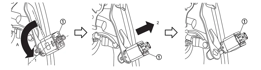
| A | : About 90 degree |
Disconnect the stroke sensor harness connector.
Remove stroke sensor if necessary.
Remove snap pin and clevis pin  from clevis of electrical brake control unit
  .
.
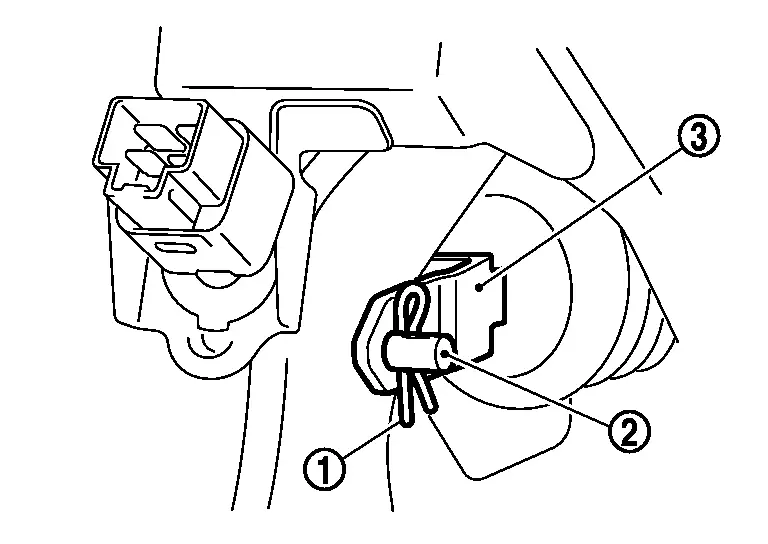
Remove harness clip from brake pedal.
Remove the electrical brake control unit mounting nuts from brake pedal assembly. Refer to Removal & Installation.
Remove the brake pedal assembly mounting bolts, and remove brake pedal assembly.
CAUTION:
Hold the electrical brake control unit so as not to drop out or contact them other parts.
Perform inspection after removal. Refer to Inspection.
INSTALLATION
Note the following, and install in the reverse order of removal.
Never reuse stop lamp switch.
Never reuse the clevis pin.
Apply the Nissan multi-purpose Special Grease No.2 or equivalent to the clevis pin and the mating faces.
 NOTE:
NOTE:The clevis pin may be inserted in either direction.
Never impact brake pedal such as drop and interference with tools and parts.
Replace brake pedal when impacting brake pedal.
Install stop lamp switch
, follow the procedure below.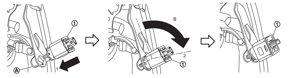
Penetrate the clip hole of stop lamp switch mounting bracket and firmly push the direction (1) the stop lamp switch against the stop lamp switch mounting bracket
 .
.B : About 90 degree Turn the stop lamp switch clockwise (2) until it stops.
Perform adjustment after installation. Refer to Adjustment.
Perform stroke sensor calibration when brake pedal assembly removed and installed, or replaced. Refer to Work Procedure.
Perform stroke sensor calibration when stroke sensor removed and installed, or replaced. Refer to Work Procedure.
 Exploded View
Stroke sensor Clevis pin Brake pedal assembly Brake pedal pad Snap pin Stop lamp switch : N·m (kg-m, ft-lb) : N·m (kg-m, in-lb) : Apply Nissan multi-purpose Special Grease No.2 or equival ...
 Inspection
INSPECTION AFTER REMOVAL
Check the brake pedal assembly for bend, damage, and cracks on the welded parts. If any is found, replace brake pedal assembly. ...
Other materials:
Removal & Installation
WARNING:
REMOVAL
Remove engine cover. Refer to Removal and Installation.
Remove ignition coil. Refer to Removal and Installation.
Remove spark plug with a spark plug wrench (commercial service tool).
: 14 mm (0.55 in)
INSTALLATION
Install in the reverse order of removal. ...
Normal Operating Condition
LED HEADLAMP
LED brightness and color may slightly change until the temperature becomes stable. This is not malfunction.
Illumination time lag may occur between right and left. This is not malfunction.
Brightness may be reduced due to aged deterioration of LED.
INTELLIGENT AUTO LIGHT SYSTEM
The hea ...
Symptom Table
LOW TIRE PRESSURE WARNING LAMP SYMPTOM CHART
Diagnosis items Symptom
(Ignition switch ON) Low tire pressure warning lamp Cause Action Low tire pressure warning lamp
The low tire pressure warning lamp illuminates for 1 second, then turns OFF.
Wake-up operation for all tire pressure sensors at ...

0.0054