
Nissan Armada 2025-2026 Service and Repair Manual: Removal and Installation
REMOVAL
Remove front evaporator. Refer to Removal and Installation.
Disconnect sub harness connector  from intake sensor harness connector.
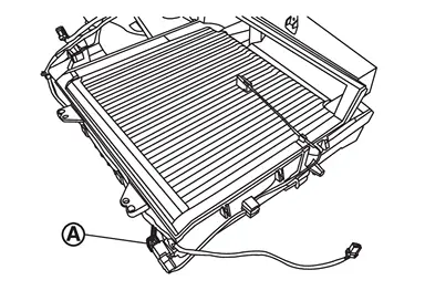
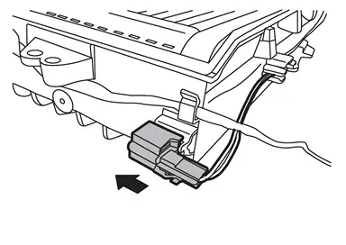
Remove intake sensor harness connector from front case upper.
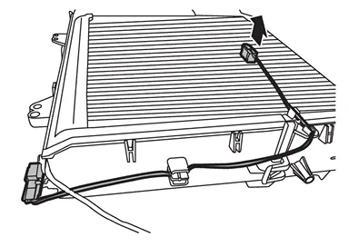
Remove intake sensor from front evaporator.
CAUTION:
Mark the mounting position of intake sensor bracket prior to removal so that the reinstalled sensor can be located in the same position.
Never damage the evaporator core.
INSTALLATION
Note the following item, and then install in the reverse order of removal.
CAUTION:
Never rotate the bracket insertion part when removing and installing the intake sensor.
 Exploded View
Refer to Exploded View. ...

Other materials:
Wiring Diagram
BATTERY POWER SUPPLY FUSE No. 27
Click link to Wiring Diagram.
BATTERY POWER SUPPLY FUSE No. 30
Click link to Wiring Diagram.
BATTERY POWER SUPPLY FUSE No. 55
Click link to Wiring Diagram.
BATTERY POWER SUPPLY FUSE No. 58
Click link to Wiring Diagram.
BATTERY POWER SUPPLY FUSE No. 133
Click link to ...
Trouble Diagnosis Flow Chart
DESCRIPTION
DETAIL OF TROUBLE DIAGNOSIS FLOW CHART
INTERVIEW WITH CUSTOMER
Interview with the customer is important to detect the root cause of CAN communication system errors and to understand vehicle condition and symptoms for proper trouble diagnosis.
Points in interview
What: Parts name, system ...
Diagnosis Procedure
CHECK INTELLIGENT KEY SYSTEM SYMPTOM TABLE
Check Intelligent Key system symptom table. Refer to Diagnosis Procedure.
>>
GO TO 2.
CHECK OUTSIDE KEY ANTENNA
Use SIGNAL TECH II to check each outside key antenna. For the inspection method and how to use SIGNAL TECH II, refer to “NISSAN/INFINIT ...

0.0055