
Nissan Armada 2025-2026 Service and Repair Manual: Trouble Diagnosis Flow Chart
DESCRIPTION
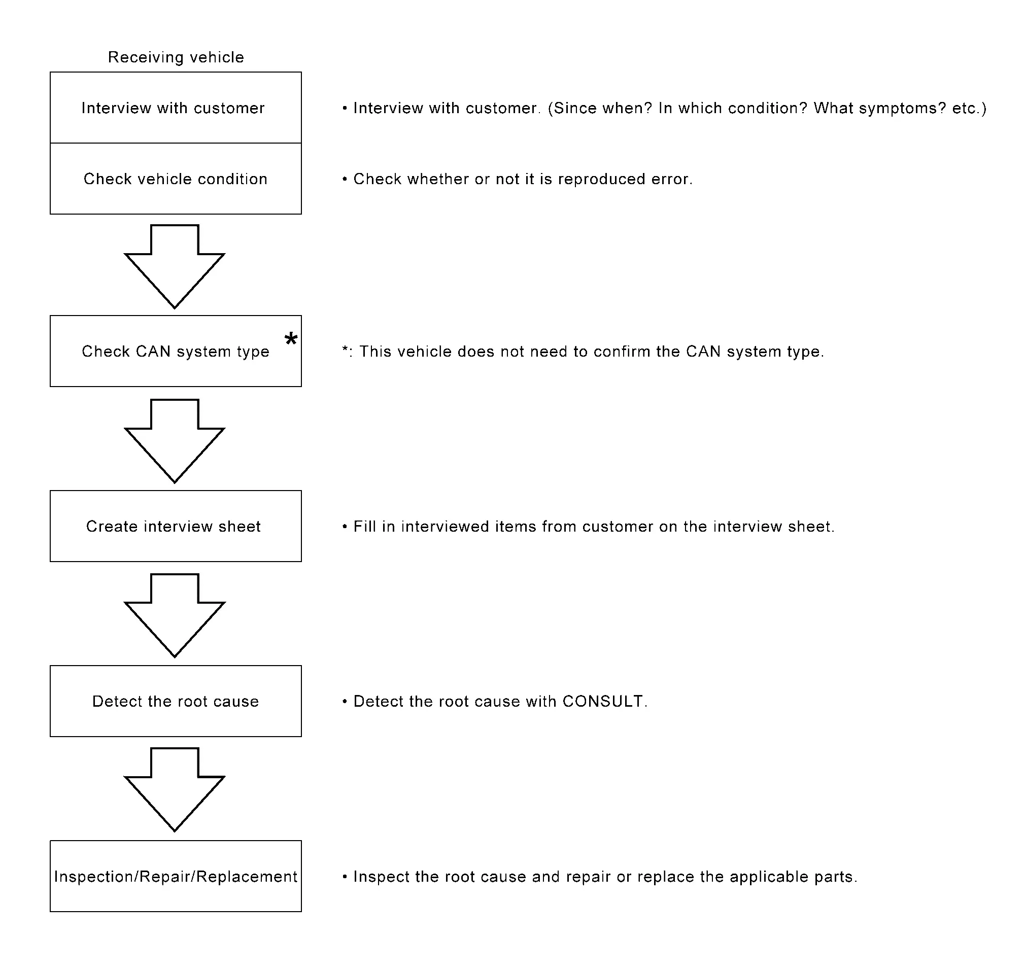
DETAIL OF TROUBLE DIAGNOSIS FLOW CHART
INTERVIEW WITH CUSTOMER
Interview with the customer is important to detect the root cause of CAN communication system errors and to understand vehicle condition and symptoms for proper trouble diagnosis.
Points in interview
What: Parts name, system name
When: Date, Frequency
Where: Road condition, Place
In what condition: Driving condition/environment
Result: Symptom
Notes for checking error symptoms:
Check normal units as well as error symptoms.
Example: Circuit between ECM and the combination meter is judged normal if the customer indicates tachometer functions normally.
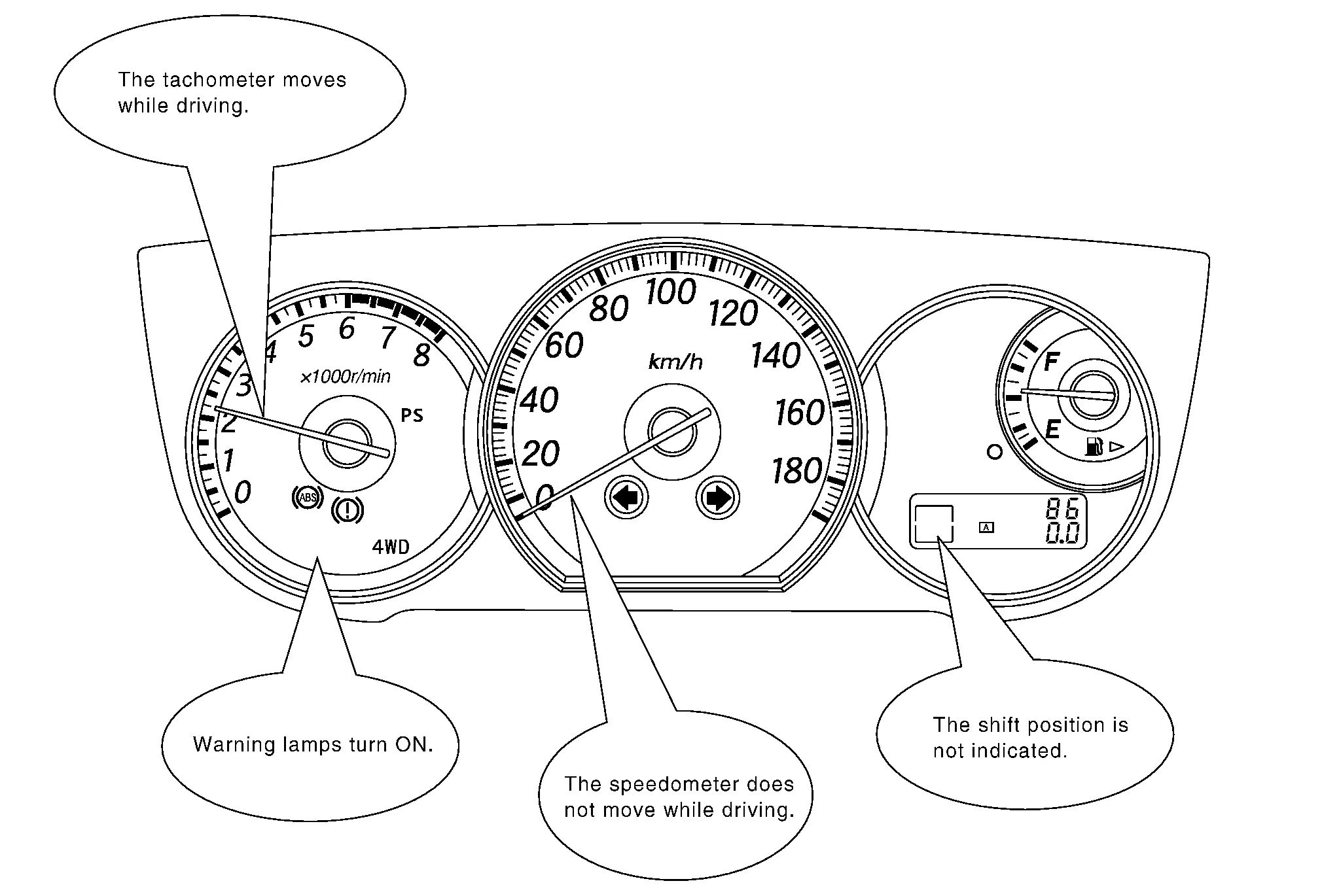
When a CAN communication system error is present, multiple control units may malfunction or go into fail-safe mode.
Indication of the combination meter is important to detect the root cause because it is the most obvious to the customer, and it performs CAN communication with many units.
GO TO 2.
INSPECTION OF Vehicle CONDITION
Check whether the symptom is reproduced or not.
 NOTE:
NOTE:
Do not turn the ignition switch OFF or disconnect the 12V battery cable while reproducing the error. The error may temporarily correct itself, making it difficult to determine the root cause.
>>GO TO 3.
CHECK OF CAN SYSTEM TYPE (HOW TO USE CAN SYSTEM TYPE SPECIFICATION CHART)
NOTE:
This vehicle does not need to confirm the CAN system type.
>>GO TO 4.
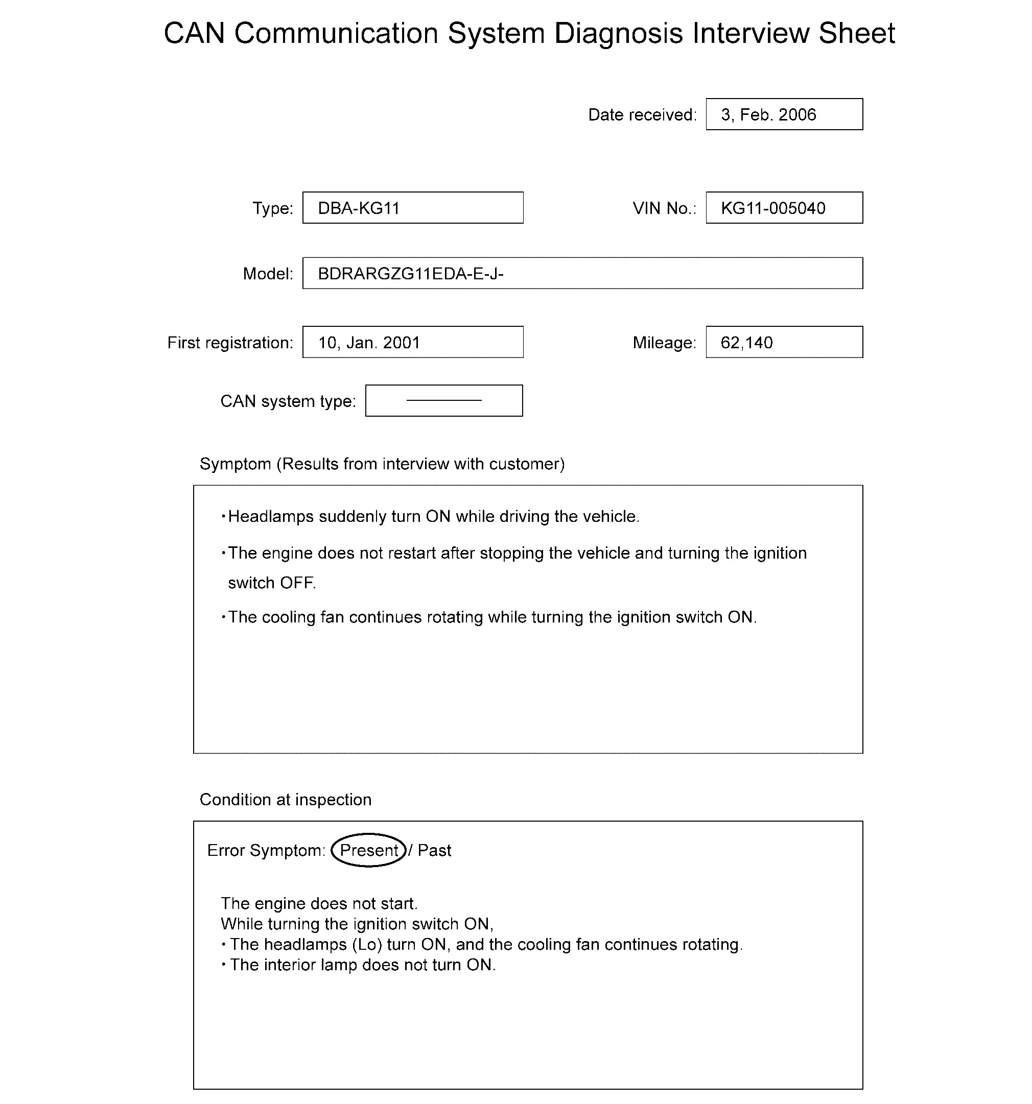
CREATE INTERVIEW SHEET
Fill out the symptom described by the customer and vehicle condition on the interview sheet.
NOTE:
Interview Sheet (Example)
GO TO 5.
DETECT THE ROOT CAUSE
"Network Diagnosis" function of CONSULT detects a root cause.
>>GO TO 6.
REPAIR OR REPLACE MALFUNCTIONING PART
Repair or replace malfunctioning parts identified by "Network Diagnosis" function of CONSULT.
Vehicle CAN communication circuit>>Refer to Vehicle CAN Communication Circuit.
ITS CAN communication circuit>>Refer to ITS CAN Communication Circuit.
Chassis CAN communication circuit>>Refer to Chassis CAN Communication Circuit.
Drivetrain CAN communication circuit>>Refer to Drivetrain CAN Communication Circuit.
Engine CAN communication circuit>>Refer to Engine CAN Communication Circuit.
IT CAN communication circuit>>Refer to IT CAN Communication Circuit.
Diagnostic CAN communication circuit>>Refer to Diagnostic CAN Communication Circuit.


Other materials:
Removal and Installation
REMOVAL
Remove front center console body assembly. Refer to Removal and Installation.
Press the power socket fixing pawls from the back of the front center console body assembly to remove the power socket.
: Pawl
INSTALLATION
Note the following, and then install in the reverse order of removal. ...
Inspection
INSPECTION AFTER REMOVAL
When turn the shaft in direction , check returning to direction by spring power.
CAUTION:
The maximum turning force shall be 5 N·m (0.51 kg-m, 44 in-lb).
When turn the shaft in direction , check locking the shaft. INSPECTION AFTER INSTALLATION
ADJUSTMENT AFTER INSTALLATIO ...
How to park with predictive course lines
WARNING
If non-standard tire sizes are installed on the Nissan Armada, the predictive
course lines may not display accurately.
On slippery or snow-covered roads, the Nissan Armada predicted path may
differ from the actual vehicle movement.
If the Nissan Armada battery is disconnected o ...

0.0053