
Nissan Armada 2025-2026 Service and Repair Manual: Setting
 NOTE:
NOTE:
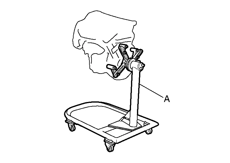
Explained here is how to disassemble with engine stand supporting transmission surface. When using a different type of engine stand, note the difference in the steps, etc.
Remove the engine assembly from the vehicle. Refer to Unit Removal & Installation.
Remove the parts that may restrict installation of engine to a widely use engine stand.
NOTE:
The procedure is described assuming that you use a widely use engine stand holding the surface, to which transmission is installed.
Fix crankshaft with a ring gear stopper [SST: KV10118600 (NI-48641)], and remove mounting bolts.
Loosen mounting bolts in diagonal order.
Check for deformation or damage of drive plate.
CAUTION:
Never disassemble drive plate.
Never place drive plate with signal plate facing down.
When handling signal plate, take care not to damage or scratch it.
Handle signal plate in a manner that prevents it from becoming magnetized.
Lift the engine with hoist to install it onto the widely use engine stand.
CAUTION:
Use an engine stand that has a load capacity [220 kg (485 lb) or more] large enough for supporting the engine weight.
If the load capacity of the stand is not adequate, remove the following parts beforehand to reduce the potential risk of overturning the stand.
Remove intake manifold. Refer to Removal and Installation.
Remove fuel injector and fuel tube assembly. Refer to Removal and Installation.
Remove ignition coil. Refer to Removal and Installation.
Remove rocker cover. Refer to Removal and Installation.
Other removable brackets.
NOTE:The figure shows an example of widely use engine stand (A) that can hold mating surface of transmission with drive plate removed.
CAUTION:
Before removing the hanging chains, check the engine stand is stable and there is no risk of overturning.
Drain engine oil. Refer to Draining.
Drain engine coolant by removing water drain plug  from both sides of the cylinder block as shown in the figure.
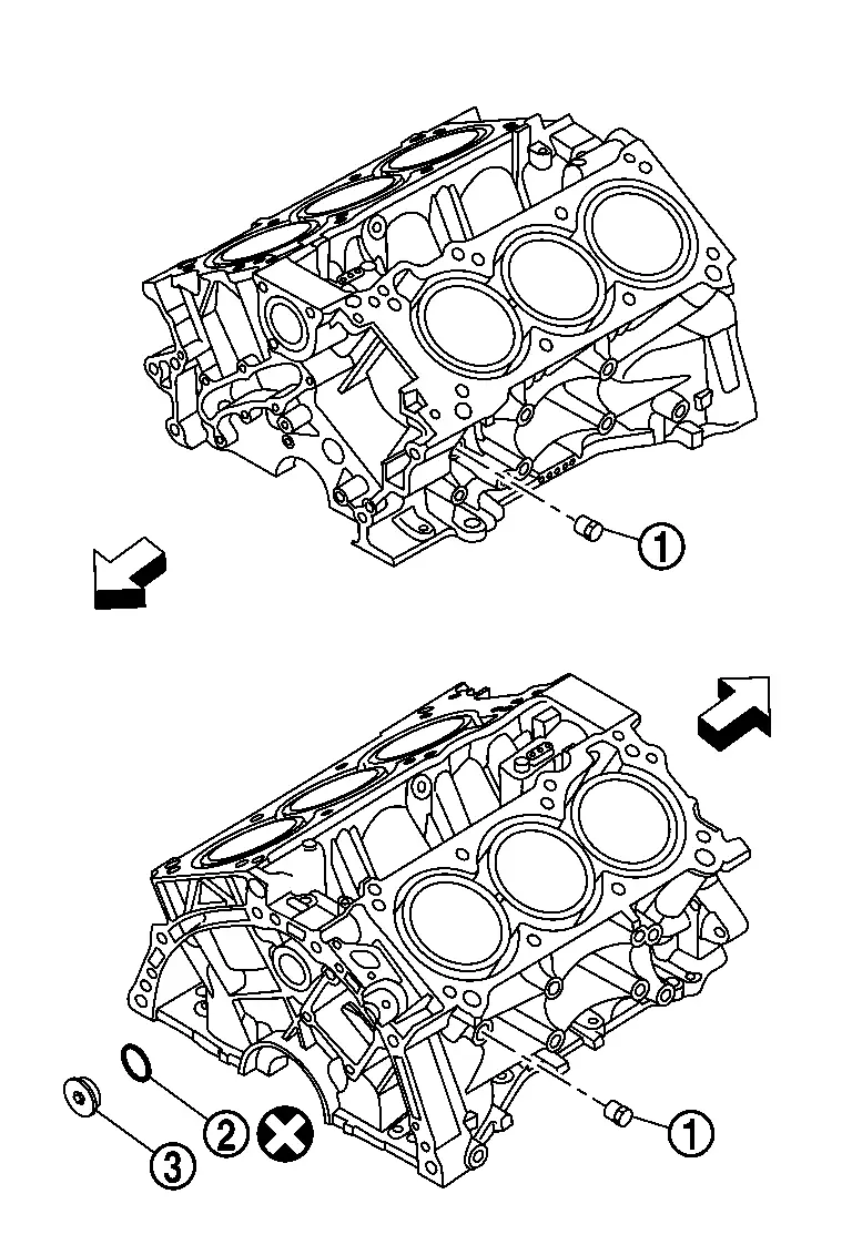
 | : Washer |
 | : Plug |
 | : Always replace after every disassembly |
 | : Engine front |

 Drive Plate
...
Other materials:
Precaution for Supplemental Restraint System (SRS) "AIR BAG" and "SEAT BELT PRE-TENSIONER"
The Supplemental Restraint System such as “AIR BAG� and “SEAT BELT PRE-TENSIONER�, used along with a front seat belt, helps to reduce the risk or severity of injury to the driver and front passenger for certain types of collisions.
Information necessary to service the system safely is inclu ...
Comparison of Pulling Methods
(1) HYDRAULIC RAM TYPE
In this method, the pressing force of a hydraulic ram is converted to a pulling force by a chain.
Pulling points on the body may be added easily, and there is more freedom to select the pulling direction.
The pulling direction changes during pulling.
Difficult to simultaneous ...
Chassis control
Basic information
The Nissan Armada chassis control system is an advanced electronic module designed
to enhance driving stability and comfort by managing multiple dynamic functions.
Intelligent Trace Control
Intelligent Trace Control
The Intelligent Trace Control system in the Nissan Arma ...

0.0053