
Nissan Armada 2025-2026 Service and Repair Manual: SONAR SENSOR (FRONT) : Removal & Installation
WARNING:
REMOVAL
Center sensor
 NOTE:
NOTE:
When removing the sensor holder, remove the front bumper. Refer to Removal and Installation.
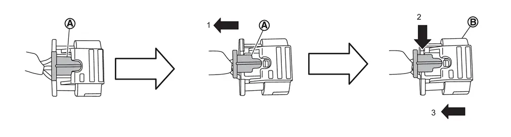
Disconnect sonar sensor harness connector , follow the procedure below.Slide the lock  of the connector toward the direction (1). Keep pushing (2) in the lock of connector and remove the harness connector
  to ward the direction (3).
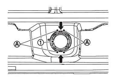
Unhook the pawls in the direction ( ) and remove the sonar sensor
  from the sensor holder.
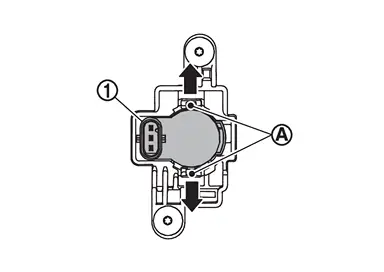
Remove the mounting screws , and remove the sensor holder from the front bumper fascia.
NOTE:
When removing the sensor finisher, remove the front bumper. Refer to Removal and Installation.
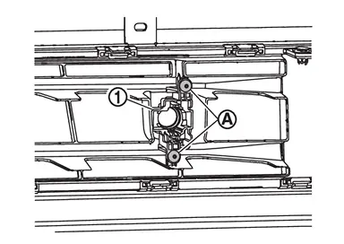
Disconnect sonar sensor harness connector, follow the procedure below.Slide the lock of the connector toward the direction (1). Keep pushing (2) in the lock of connector and remove the harness connector to ward the direction (3).
Unhook the pawls in the direction () and remove the sonar sensor from the sensor finisher.
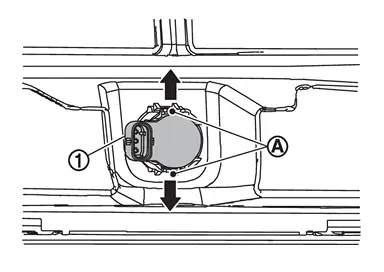
Unhook the pawls in the direction () and remove the sensor holder from the front bumper fascia.
Corner sensor
NOTE:
When removing the sensor holder, remove the front bumper. Refer to Removal and Installation
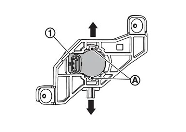
Remove the mounting screws , and remove the sensor holder from the front bumper fascia.
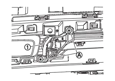
NOTE:
When removing the sensor holder, remove the front bumper. Refer to Removal and Installation.
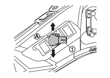
Remove the sensor holder from the front bumper fascia. (Without welding type)
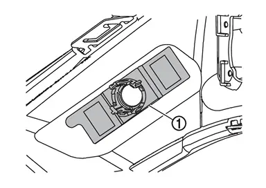
INSTALLATION
CAUTION:
Check sonar sensor packing for damage before installation.
Check that the packing is properly installed to the sonar sensor.
Install it so that the connector of the sensor turns to the arrow direction of the figure.
CITY MODELS
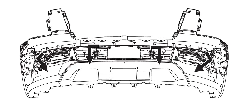
 | : Connector direction | ||||
OFF ROAD MODELS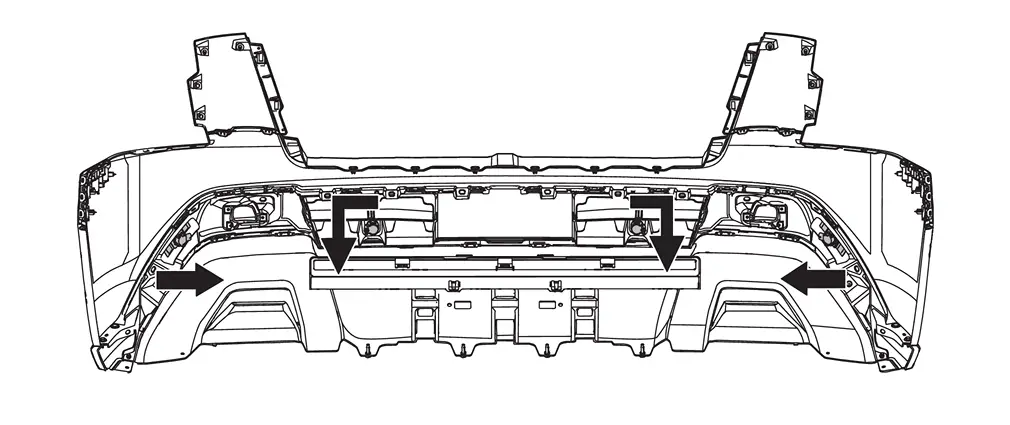
| : Connector direction | ||||
Center sensor
Install in the reverse order of removal.
Corner sensor
Install in the reverse order of removal.
Install in the reverse order of removal when install only the sensor.
Follow the procedure below when replace the sensor holder.
CAUTION:
Never reuse the sensor holder. Always use new sensor holder when removing and replacing sensor holder and/or front bumper facia.
Hook the pawls
to install the sonar sensor to the sensor holder.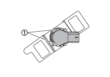
Degrease and clean the inner side of the bumper fascia base line
and then apply primer (3M K500,K520 or equivalent) on the sensor holder installing face , which is shown as on the figure.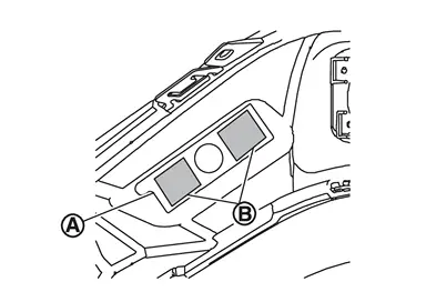
CAUTION:
Never apply two coats of primer. Applying two coats or more of primer results in excessively thick film and this may allow the sensor holder to come off from primer under exfoliation.
Dry the primer for more than 3 minutes and peel off the double sided tape
releasing paper (film) and then taking precautions not to contact the bumper with the double sided tape ( on the figure), bend the sensor holder to the arrow direction as shown on the figure .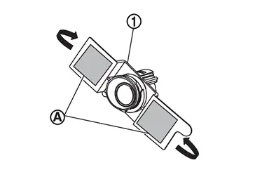
Match the sonar sensor part
shown on the figure, to the sensor installing hole of the bumper fascia.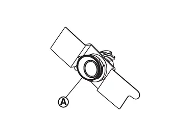
Remove the sensor from the sensor holder and press the adhesion face (part
on figure) throughout with your thumb for more than 2 seconds and pressure bond the sensor holder [Target pressure: 50 N (5.1kg, 11.3 lb)].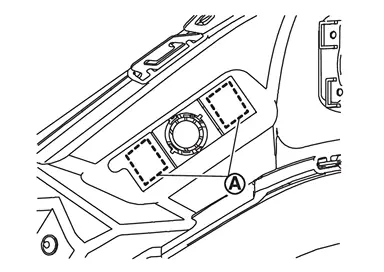
CAUTION:
When the temperature is less than 15°C (59°F), use a drier etc., to warm the adhesion face and proceed the work.
After installing the sensor holder, leave it at least for 2 - 3 hours.
Hook the pawls
to install the sonar sensor to the sensor holder.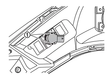
Shake the part
of the sensor holder shown on the figure up and down and then right and left to confirm that the holder has been installed (bonded) firmly.Connect connector to the sonar sensor.
Install the front bumper. Refer to Removal and Installation.
 SONAR SENSOR (FRONT) : Exploded View
CITY MODELS
Front bumper fascia Corner sensor front LH holder Corner sensor front LH Center sensor front LH holder Center sensor front LH Center sensor front RH holder Center sensor front RH ...

Other materials:
Diagnosis Procedure
CHECK LIFTING MECHANISM
Check for the following.
Mechanism deformation or pinched foreign materials.
Interference with other parts because of poor installation.
Is the inspection result normal?
YES>>
GO TO 2.
NO>>
Repair or replace the malfunctioning parts.
CHECK LIFTING SWITCH
Check ...
Ball Joint
Item Standard Swing torque 0.5 – 6.4 N·m (0.06 – 0.65 kg-m, 5 – 56 in-lb) Measurement on spring balance (groove position) Suspension arm 7.9 – 53.2 N (0.81 – 5.42 kg, 1.78 – 11.95 lb) Front lower link 5.9 – 74.5 N (0.61 – 7.59 kg, 1.33 – 16.74 lb) Rotating torque Suspen ...
Warning/indicator lights (red)
Brake warning light
or
In the Nissan Armada, the brake warning light is a critical safety indicator
that helps monitor the condition of the braking system. When the ignition switch
is turned to the ON position, this light should illuminate briefly for a few seconds
and then turn off, ...

0.005