Exploded View
REMOVAL
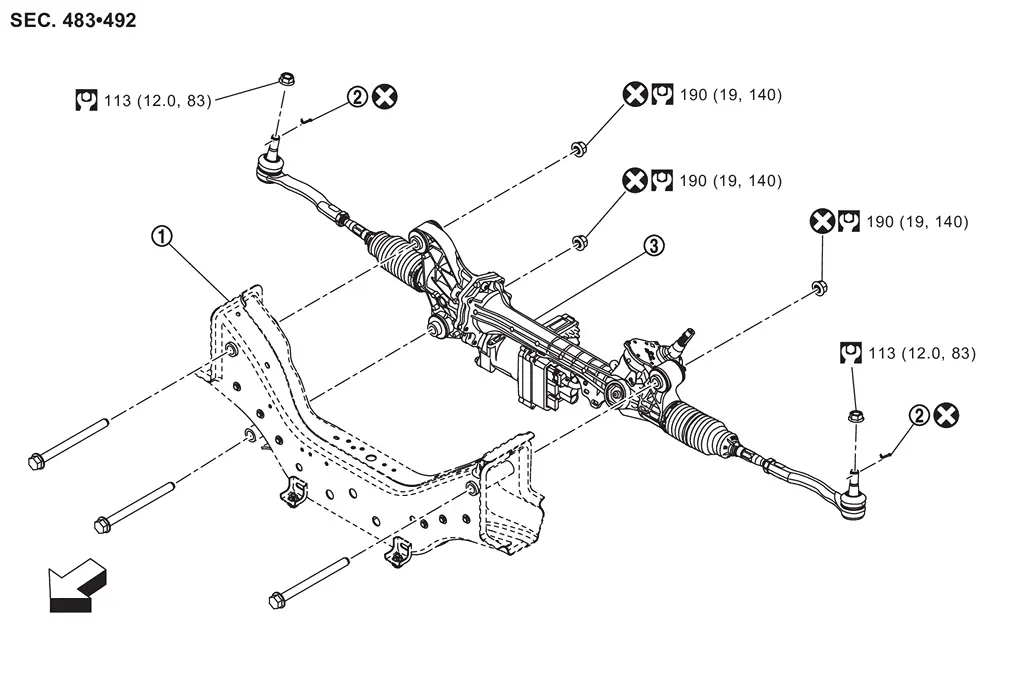
 |
Member |  |
Cotter pin |  |
Steering gear assembly |
| : vehicle front | |||||
 |
: N·m (kg-m, ft-lb) | ||||
 |
: Always replace after every disassembly. | ||||
DISASSEMBLY
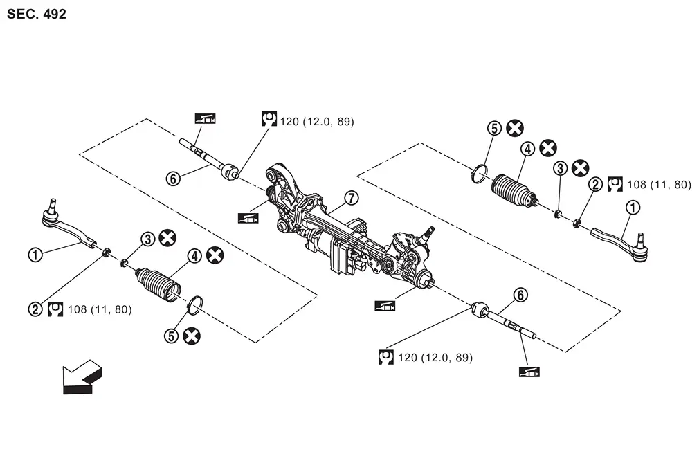
|
Outer socket | |
Outer socket lock nut | |
Boot clamp (small diameter) |
 |
Boot |  |
Boot clamp (large diameter) |  |
Inner socket |
 |
Gear housing assembly | ||||
|
: N·m (kg-m, ft-lb) | ||||
 |
: Apply RheoGel TEK676. | ||||
|
: Always replace after every disassembly. | ||||
| : vehicle front | |||||
CAUTION:
Never apply the grease to the surface between steering rack and inner socket screw part.
Removal and Installation
WARNING:
-
Jacking up or lift up the vehicle may the vehicle height to go down which cause a personal injury and/or damage to the air suspension component parts. Refer to Precaution for when Jacking and Lifting Up the vehicle with Electronic Air Suspension System.
CAUTION:
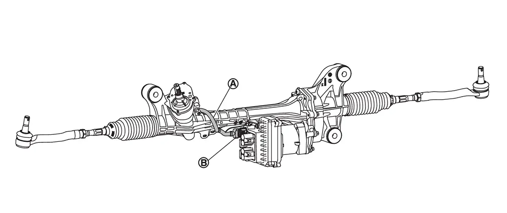
Never disconnect or pull the torque sensor harness  and harness connector
  .
.
REMOVAL
Set vehicle to the straight-ahead position.
Remove 12V battery terminal. Refer to Removal and Installation.
Remove tires. Refer to ROAD WHEEL TIRE : Removal & Installation.
Remove cotter pins and mounting nuts, and separate outer socket from steering knuckle.
Remove outer sockets, outer socket lock nuts, boots, boot clamps, and Inner sockets if necessary. Refer to Disassembly and Assembly.
Remove front under cover. Refer to Removal and Installation.
Remove engine under cover. Refer to Removal and Installation.
Disconnect steering gear assembly harness connectors.
Remove harness clip from steering gear assembly.
Remove lower joint from steering gear assembly.
Remove air inlet tube 1. Refer to Removal & Installation.
Remove steering gear assembly mounting bolts and nuts.
Remove steering gear assembly from vehicle.
INSTALLATION
Note the following, and install in the reverse order of removal.
CAUTION:
-
Spiral cable may be cut if steering wheel turns while separating steering column assembly and steering gear assembly. Always fix the steering wheel using string to avoid turning.
-
Never damage the boot band when installing mounting bolts and nuts.
-
Before installation, check that the tilt position is at the middle level.
-
To install the steering gear assembly, after inserting the mounting bolts, temporarily tighten the mounting nuts using the tightening method and numerical order shown below, and then tighten to the specified torque.
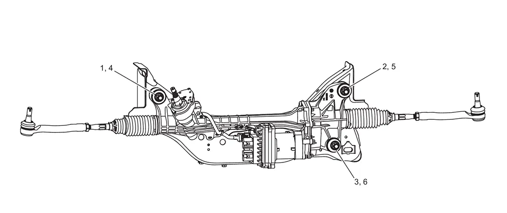
Temporary tightening : 1 → 2 → 3 Final tightening (Specified torque) : 4 → 5 → 6 -
Perform final tightening of nuts and bolts on each part under unladen conditions with tires on level ground when removing steering gear assembly. Check wheel alignment.
-
Rotate steering wheel to check for decentered condition, binding, noise or excessive steering effort.
-
Perform inspection after installation. Refer to Inspection.
Disassembly and Assembly
DISASSEMBLY
CAUTION:
Disassemble and assemble steering gear assembly by fixing the mounting area with a vise using copper plates.
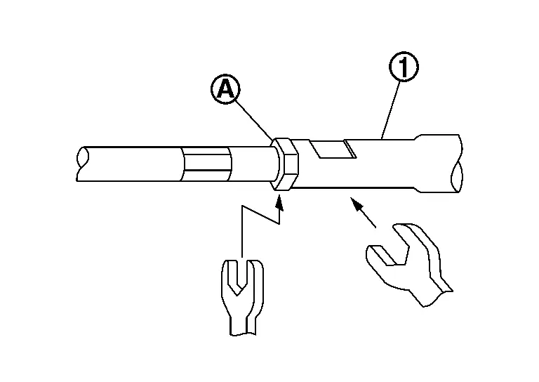
Loosen outer socket lock nut, and remove outer socket.
CAUTION:
To prevent damage, hold outer socket across flats using suitable tool while loosening outer socket lock nut .
Remove boot clamps, and then remove boot from inner socket and housing.
CAUTION:
Never damage inner socket part of gear housing assembly when removing boot. Steering gear assembly must be replaced if gear housing assembly are damaged because it may cause foreign material interfusion.
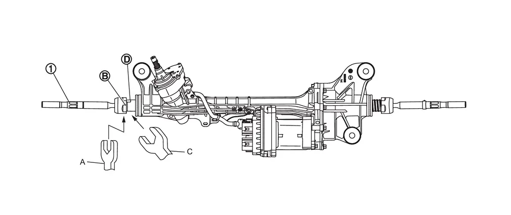
Remove the left inner socket.
CAUTION:
To prevent damage to the steering gear when removing the inner socket , hold suitable tool (C) across steering gear flats  while turning suitable tool (A) across inner socket flats .
Remove the right inner socket.
CAUTION:
-
To prevent damage to the steering gear when removing the inner socket
, hold suitable tool (C) across steering gear flats while turning suitable tool (A) across inner socket flats .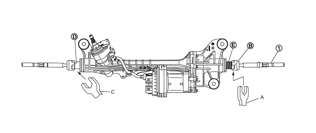
-
Never remove the inner socket by fixing part
 with a suitable tool.
Perform inspection after disassembly. Refer to Inspection.
ASSEMBLY
Install left inner socket. Tighten to specified torque. Refer to Exploded View.
CAUTION:
To prevent damage to the steering gear when installing the inner socket , hold suitable tool (C) across steering gear flats while turning suitable tool (A) across inner socket flats .
Install right inner socket. Tighten to specified torque. Refer to Exploded View.
CAUTION:
-
To prevent damage to the steering gear when installing the inner socket
, hold suitable tool (C) across steering gear flats while turning suitable tool (A) across inner socket flats . -
Never install the inner socket by fixing part
with a suitable tool.
Apply recommended grease to part of inner socket.
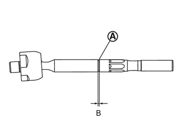
| Use RheoGel TEK676. | |
| B (groove part) | : 0.2 mm (0.008 in) |
Apply recommended grease to part of gear housing assembly.
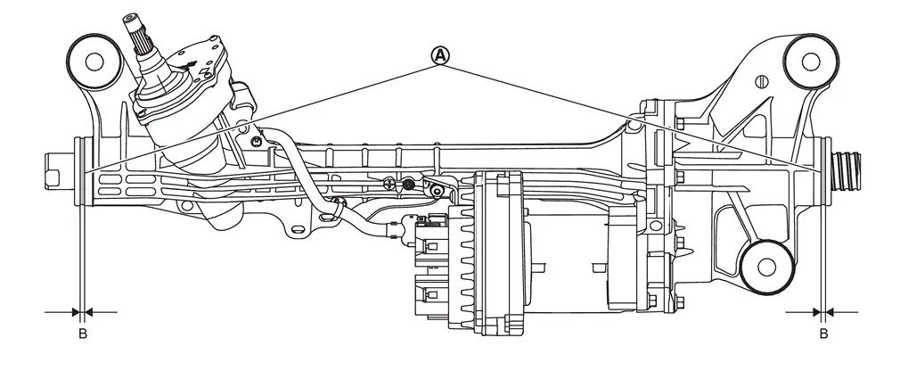
| Use RheoGel TEK676. | |
| B | : 4 mm (0.16 in) |
Install boot to inner socket and gear housing.
Install boot clamp (large diameter) to boot using boot band crimping tool [SST: KV40107300 (NI-51751)] (A).
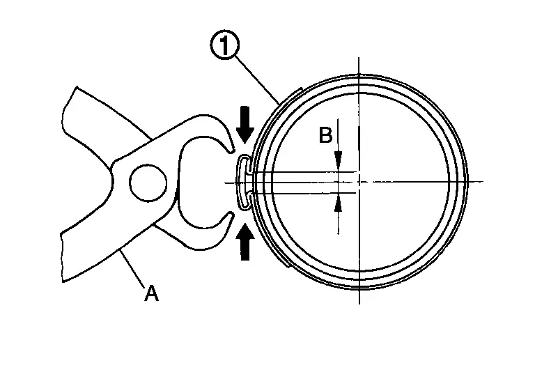
CAUTION:
-
Never reuse boot clamp (large diameter).
-
Install boot clamp (large diameter) securely to boot groove, and crimp it so as to have clearance (B) of 5 mm (0.20 in) or less as shown.
Install boot clamp (small diameter) to boot.
CAUTION:
Never reuse boot clamp (small diameter).
Adjust inner socket to standard length (A), and then tighten lock nut to the specified torque. Check length again after tightening lock nut.
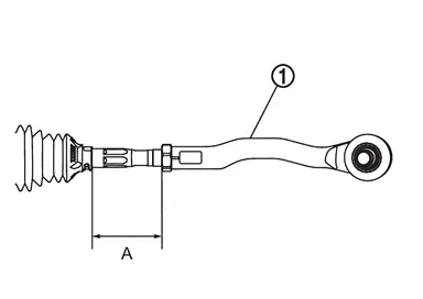
|
: Outer socket |
| Inner socket length (A) | : Steering Gear and Linkage |
CAUTION:
-
When tightening the lock nut
, be sure to fix outer socket with a wrench or an equivalent to prevent the ball joint from getting contact with the knuckle. -
Adjust toe-in after this procedure. The length achieved after toe-in adjustment is not necessarily the above value.
Inspection
INSPECTION AFTER DISASSEMBLY
Boot
-
Check boot for cracks, and replace it if a malfunction is detected.
Gear Housing Assembly
-
Check gear housing assembly for damage and scratches. Replace if there are any abnormal conditions.
Outer Socket and Inner Socket
-
Check the following items and replace the component if it does not meet the standard.
BALL JOINT SWINGING FORCE
-
Hook a pull gauge [SST: — (NI-44372)] at the point shown in the figure and pull the pull gauge. Make sure that the pull gauge reads the specified value when ball stud and inner socket start to move. Replace outer socket and inner socket if they are outside the standard.
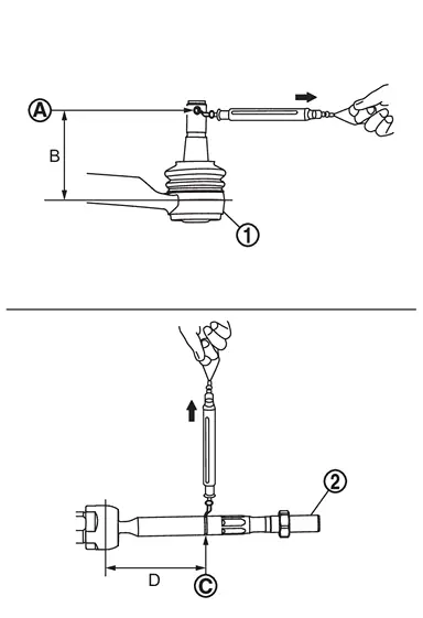
Measuring point of outer socket -
Ball stud cotter pin hole
-
Moment arm length (B): 71.4 mm (2.811 in)
Measuring point of inner socket -
Point shown in the figure

-
Moment arm length (D): 108.4 mm (4.27 in)
Swinging force : Refer to Steering Gear and Linkage -
BALL JOINT ROTATING TORQUE
-
Make sure that the reading is within the following specified range using suitable tool (A). Replace outer socket if the reading is outside the specification.
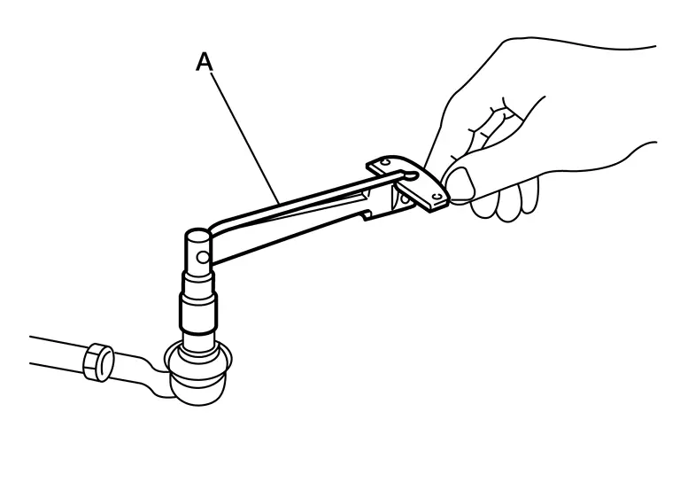
Rotating torque : Refer to Steering Gear and Linkage
BALL JOINT AXIAL END PLAY
-
Apply an axial load of 490 N (50 kg, 110 lb) to ball stud. Using a dial gauge, measure amount of stud movement, and then make sure that the value is within the following specified range. Replace outer socket
and inner socket if the measured value is outside the standard.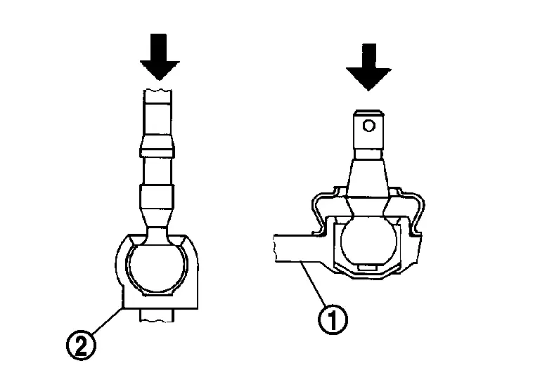
Axial end play : Steering Gear and Linkage
INSPECTION AFTER INSTALLATION
-
Check if steering wheel turns smoothly when it is turned several times fully to the end of the left and right.
-
Check the steering wheel play, neutral position steering wheel, steering wheel turning force, and front wheel turning angle.
-
Steering wheel play: Refer to Inspection.
-
Neutral position steering wheel, steering wheel turning force, and front wheel turning angle: Refer to Inspection.
-
-
Perform "ADDITIONAL SERVICE WHEN REPLACING POWER STEERING CONTROL MODULE". Refer to Work Procedure.
-
Adjust neutral position of steering angle sensor. Refer to Work Procedure.
-
If equipped with ProPILOT Assist, perform steering torque calibration after replacing or removal and installation the steering wheel. Refer to Work Procedure.
Other materials
Diagnosis and Repair Work Flow
Work Flow
OVERALL SEQUENCEDETAILED FLOWINTERVIEW FOR MALFUNCTION
It is also important to clarify the customer concerns before starting the inspection. Interview the customer about the concerns carefully and understand the symptoms fully.
NOTE:
The customers are not professionals. Never assume that ...
Door Outside Molding
Exploded View
Front door panel
Front door outside molding
Rear door outside molding
Rear door panel
: Pawl
: vehicle front
...
Precautions
Precaution for Supplemental Restraint System (SRS) "AIR BAG" and "SEAT BELT PRE-TENSIONER"
The Supplemental Restraint System such as “AIR BAG” and “SEAT BELT PRE-TENSIONER”, used along with a front seat belt, helps to reduce the risk or severity of injury to the driver and front passenger fo ...