Exploded View
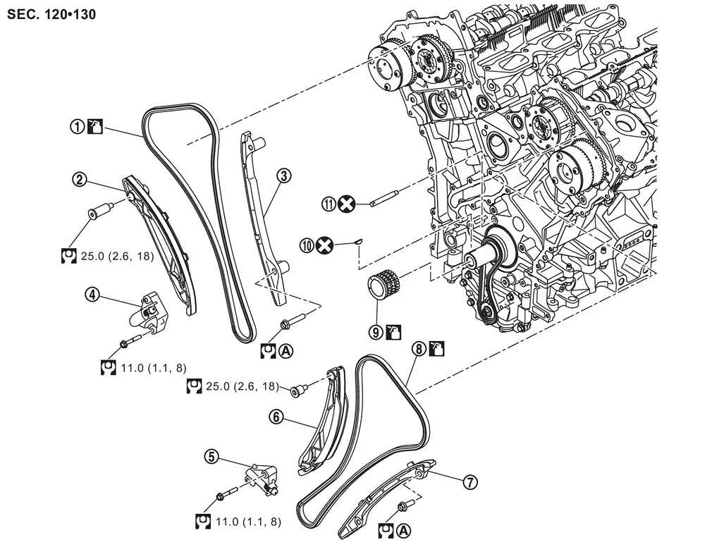
 |
Timing chain (bank 1) |  |
Timing chain slack guide (bank 1) |  |
Timing chain tension guide (bank 1) |
 |
Timing chain tensioner (bank 1) |  |
Timing chain tensioner (bank 2) |  |
Timing chain slack guide (bank 2) |
 |
Timing chain tension guide (bank 2) |  |
Timing chain (bank 2) |  |
Crankshaft sprocket |
 |
Crankshaft key |  |
Timing chain oil jet | ||
 |
Comply with the installation procedure when tightening. Refer to Removal and Installation. | ||||
 |
: N·m (kg-m, ft-lb) | ||||
 |
: Always replace after every disassembly. | ||||
 |
: Should be lubricated with oil. | ||||
Removal and Installation
WARNING:
Jacking up or lift up the vehicle may the vehicle height to go down which cause a personal injury and/or damage to the air suspension component parts. Refer to Precaution for when Jacking and Lifting Up the vehicle with Electronic Air Suspension System.
REMOVAL
Remove valve timing control covers (bank 1 and bank 2). Refer to Removal & Installation.
Remove electric intake valve timing control actuator (bank 1 and bank 2). Refer to Removal & Installation.
Remove crankshaft pulley. Refer to Removal & Installation.
Remove front cover. Refer to Removal & Installation.
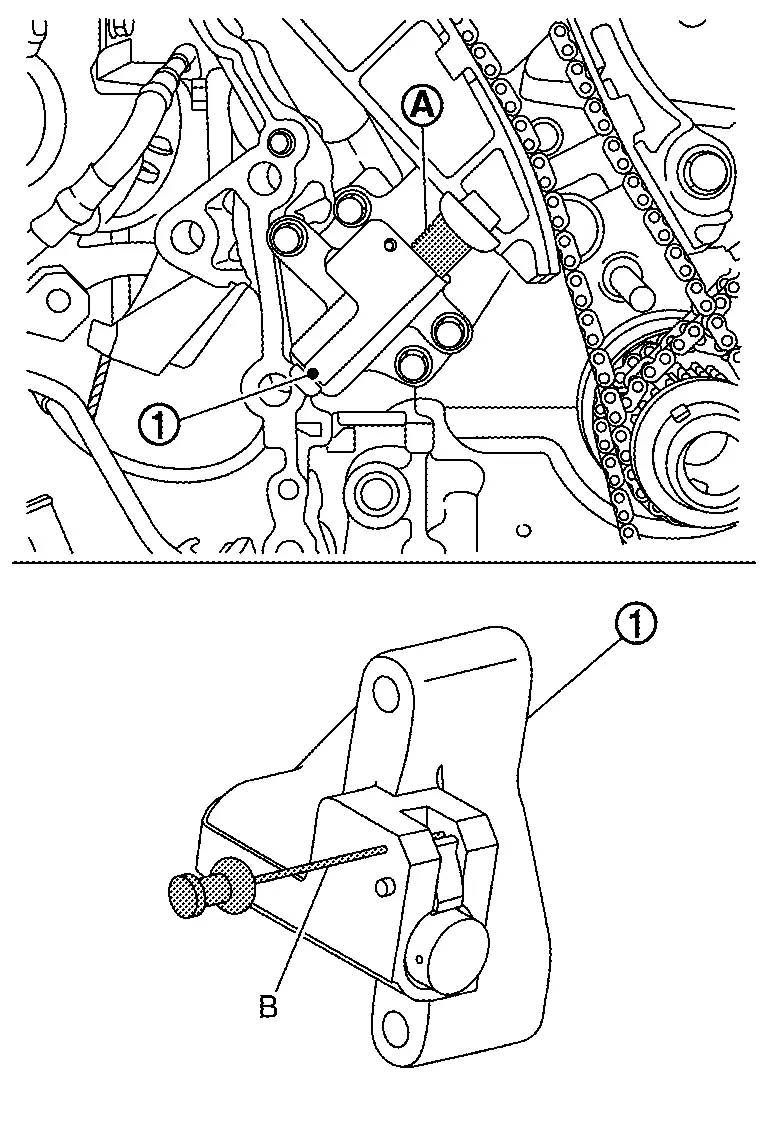
Remove timing chain tensioner as follows:Insert plunger into tensioner .
Remove timing chain tension guides and slack guides.
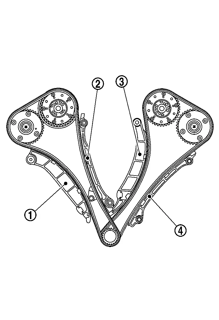
|
: Timing chain slack guide (bank 1) |
|
: Timing chain tension guide (bank 1) |
|
: Timing chain guide (bank 2) |
|
: Timing chain tension guide (bank 2) |
Remove timing chain (bank 1 and bank 2) .
Remove oil pump drive chain if necessary.
INSTALLATION
CAUTION:
Do not reuse O-rings.
 NOTE:
NOTE:
-
If a timing chain is removed, carry out the teach of “Electric IVT Control Actuator Position Learning”. Refer to Work Procedure.
-
The below figure shows the relationship between the matching mark on each timing chain and that on the corresponding sprocket, with the components installed.
Install timing chain oil jet, if removed.
CAUTION:
When removing timing chain oil jet, replace timing chain oil jet and cylinder block.
-
The direction of the timing chain oil jet must be within ±10°
 of the indicated position .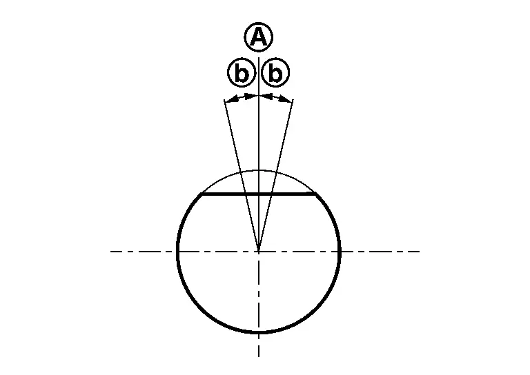
Check that dowel pin and crankshaft key are located as shown in the figure. (No. 1 cylinder at compression TDC)
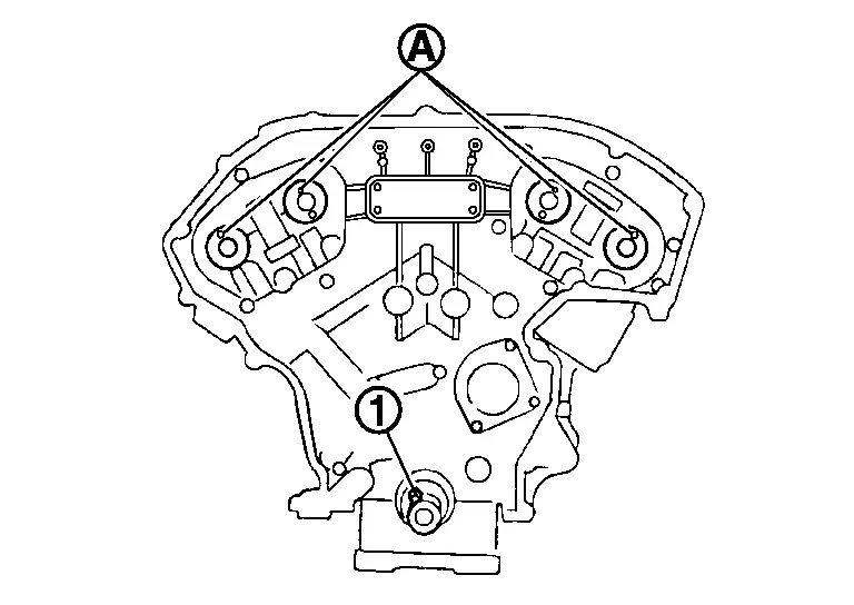
NOTE:
Though camshaft does not stop at the position as shown in the figure, for the placement of cam noses, it is generally accepted camshaft is placed for the same direction of the figure.
| Camshaft dowel pin | |
| : At cylinder head upper face side in each bank. | |
| Crankshaft key | |
| : At cylinder head side of bank 1. | |
Install timing chain as follows:
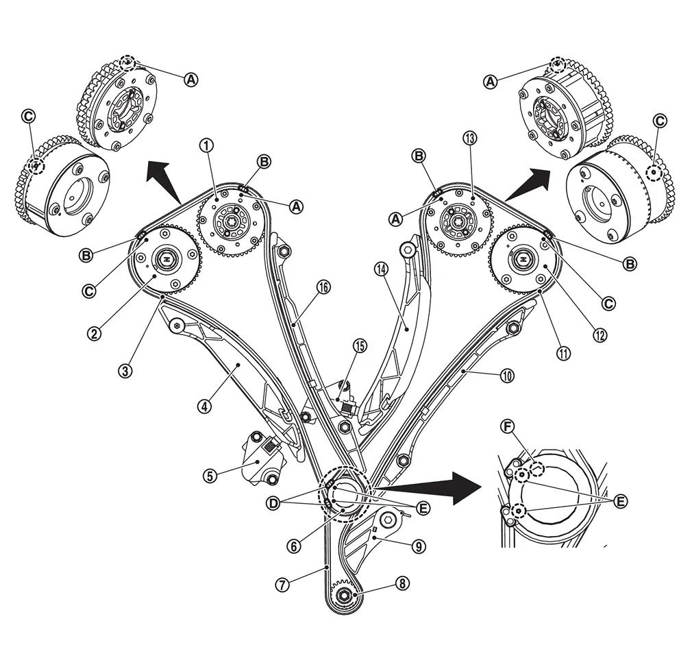
 |
Intake camshaft sprocket (bank 1) | |
Exhaust camshaft sprocket (bank 1) | |
Timing chain (bank 1) |
|
Timing chain slack guide (bank 1) | |
Timing chain tensioner (bank 1) | |
Crankshaft sprocket |
|
Oil pump drive chain | |
Oil pump sprocket | |
Oil pump drive chain tensionar |
|
Timing chain tension guide (bank 2) | |
Timing chain (bank 2) |  |
Exhaust camshaft sprocket (bank 2) |
 |
Intake camshaft sprocket (bank 2) |  |
Timing chain slack guide (bank 2) |  |
Timing chain tensioner (bank 2) |
 |
Timing chain tension guide (bank 1) | ||||
|
Matching mark (notched) |  |
Matching mark (copper link) |  |
Matching mark (notched) |
 |
Matching mark (yellow link) |  |
Matching mark (notched) |  |
Crankshaft key |
-
Insert crankshaft key
into the crankshaft key groove.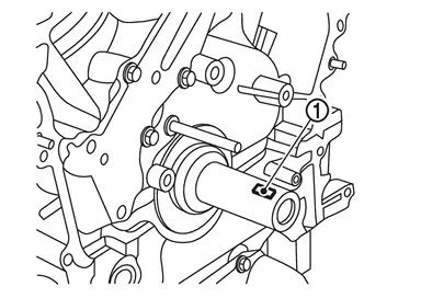
-
Install crankshaft sprocket
.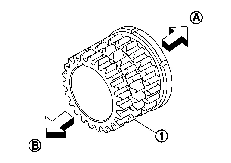
: Engine front : Crankshaft side -
Check the matching marks on crankshaft sprocket face the front of the engine.
-
- Install timing chain as follows:
-
Assemble timing chain in the order of bank 2 - bank 1.
-
Align matching marks on the camshaft sprocket (INT, EXH) and crank sprocket with the matching marks on the timing chain.
NOTE:
-
If matching marks do not line up, turn the resin coupling at the center of the intake camshaft sprocket.
-
If timing chain loosens after the timing chain is installed or if the chain guide, slack guide, or chain tensioner cannot be installed, rotate the resin coupling at the center of the intake camshaft sprocket counterclockwise until it hits.
-
-
Install timing chain tension guide.
-
Temporarily timing chain tension guide mounting bolts below in the order from 1 to 2 as shown in the figure.
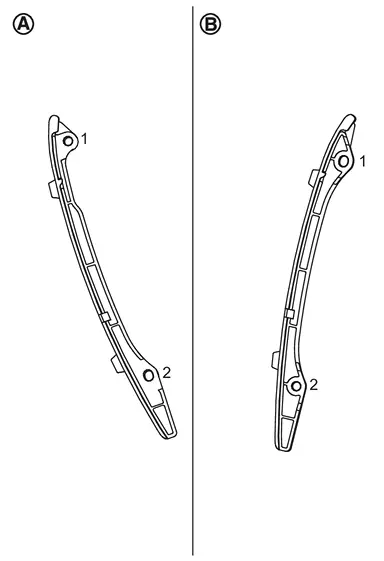
: Bank 1 side : Bank 2 side -
Tighten timing chain tension guide mounting bolts to the torque specified below in the order from 1 to 2 as shown in the figure.
: Bank 1 side : Bank 2 side : 17.7 N·m (1.8 kg-m, 13 ft-lb)
-
Install timing chain slack guide.
CAUTION:
Never overtighten slack guide mounting bolts . It is normal for a gap to exist under the bolt seats when mounting bolts are tightened to the specification.
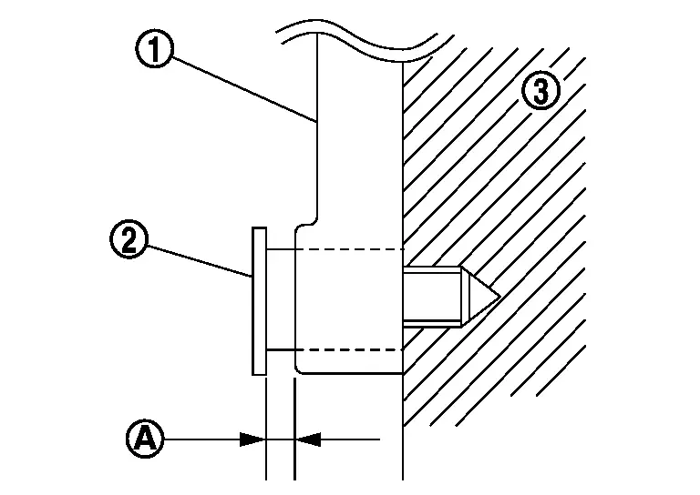
|
: Cylinder block |
Install timing chain tensioner.
Disconnect clip from chain tensioner.
Check again that the matching marks on sprockets and timing chain have not slipped out of alignment.
Install front cover. Refer to Removal & Installation.
Install crankshaft pulley. Refer to Removal & Installation.
Install electric intake valve timing control actuator (bank 1 and bank 2). Refer to Removal & Installation.
Install valve timing control covers (bank 1 and bank 2). Refer to Removal & Installation.
Inspection
INSPECTION AFTER REMOVAL
Timing Chain
Check for cracks and any excessive wear at link plates and roller links of timing chain. Replace timing chain if necessary.
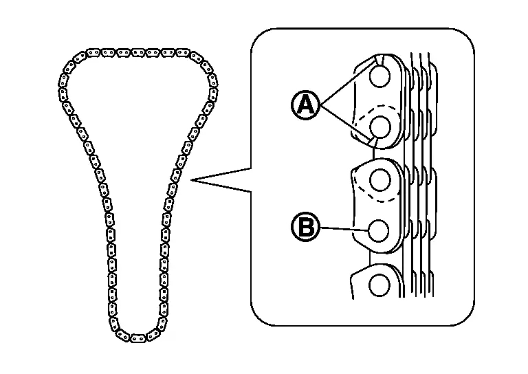
|
: Crack |
|
: Wear |
INSPECTION AFTER INSTALLATION
Inspection for Leakage
The following are procedures for checking fluids leakage, lubricates leakage.
-
Before starting engine, check oil/fluid levels including engine coolant and engine oil. If less than required quantity, fill to the specified level. Refer to Fluids and Lubricants.
-
Use procedure below to check for fuel leakage.
-
Turn ignition switch “ON” (with engine stopped). With fuel pressure applied to fuel piping, check for fuel leakage at connection points.
-
Start engine. With engine speed increased, check again for fuel leakage at connection points.
-
-
Run engine to check for unusual noise and vibration.
NOTE:
If hydraulic pressure inside chain tensioner drops after removal/installation, slack in guide may generate a pounding noise during and just after the engine start. However, this does not indicate an unusualness. Noise will stop after hydraulic pressure rises.
-
Warm up engine thoroughly to check there is no leakage of fuel, or any oil/fluids including engine oil and engine coolant.
-
Bleed air from lines and hoses of applicable lines, such as in cooling system.
-
After cooling down engine, again check oil/fluid levels including engine oil and engine coolant. Refill them to the specified level, if necessary.
Summary of the inspection items: Items Before starting engine Engine running After engine stopped Engine coolant Level Leakage Level Engine oil Level Leakage Level Transmission / transaxle fluid AT & CVT Models Leakage Level / Leakage Leakage MT Models Level / Leakage Leakage Level / Leakage Other oils and fluids* Level Leakage Level Fuel Leakage Leakage Leakage Exhaust gases — Leakage — *: Power steering fluid, brake fluid, etc.
Other materials
How to use remote keyless entry function
WARNING
In the Nissan Armada, radio frequency signals generated by the Intelligent
Key may interfere with certain medical devices.
Individuals using pacemakers or other electronic medical equipment should
consult the device manufacturer before using the Nissan Armada Intelligent Key.
...
Drive Belt Auto Tensioner and Idler Pulley
Exploded View
Idler pulley
Drive belt auto-tensioner
: N·m (kg-m, ft-lb)
: vehicle front
Removal and Installation
WARNING:
Jacking up or lift up the vehicle may the vehicle height to go down which cause a personal injury and/or damage to the air suspension component parts. ...
Head up Display Symptoms
Symptom Table
Symptom Reference
Head Up Display screen is not displayed.
Refer to Diagnosis Procedure.
Head Up Display brightness is not changed.
Refer to Diagnosis Procedure.
Head Up Display screen is not displayed in the correct position.
Refer to Diagnosis Procedure.
...