Inspection
WARNING:
-
Jacking up or lift up the vehicle may the vehicle height to go down which cause a personal injury and/or damage to the air suspension component parts. Refer to Precaution for when Jacking and Lifting Up the vehicle with Electronic Air Suspension System.
DESCRIPTION
Measure wheel alignment under unladen conditions.
 NOTE:
NOTE:
“Unladen conditions” means that fuel, engine coolant, and lubricant are full. Spare tire, jack, hand tools and mats are in designated positions.
PRELIMINARY CHECK
Check the following:
-
Tires for improper air pressure and wear. Refer to TIRE AIR PRESSURE : Service Data.
-
Road wheels for runout.
-
Wheel bearing axial end play. Refer to Inspection.
-
Ball joint axial end play of suspension arm and front lower link. Refer to Inspection.
-
Shock absorber operation.
-
Each mounting point of axle and suspension for looseness and deformation.
-
Each of front lower link, rear lower link, rear suspension member, suspension arm and shock absorber for cracks, deformation, and other damage.
-
vehicle height (posture).
-
After setting the vehicle to the normal height, and adjust th wheel alignment. (With dynamic digital suspension and electronic air suspension)
-
GENERAL INFORMATION AND RECOMMENDATIONS
-
A four-wheel thrust alignment should be performed.
-
This type of alignment is recommended for any NISSAN/INFINITI vehicle.
-
The four-wheel “thrust” process helps ensure that the vehicle is properly aligned and the steering wheel is centered.
-
The alignment rack itself should be capable of accepting any NISSAN/INFINITI vehicle.
-
The rack should be checked to ensure that it is level.
-
-
Make sure the machine is properly calibrated.
-
Your alignment equipment should be regularly calibrated in order to give correct information.
-
Check with the manufacturer of your specific equipment for their recommended Service/Calibration Schedule.
-
ALIGNMENT PROCESS
IMPORTANT:
Use only the alignment specifications listed in this Service Manual.
-
When displaying the alignment settings, many alignment machines use “indicators”: (Green/red, plus or minus, Go/No Go). Never use these indicators.
-
The alignment specifications programmed into your machine that operate these indicators may not be correct.
-
This may result in an ERROR.
-
-
Most camera-type alignment machines are equipped with both “Rolling Compensation” method and optional “Jacking Compensation” method to “compensate” the alignment targets or head units. “Rolling Compensation” is the preferred method.
-
If using the “Rolling Compensation” method, after installing the alignment targets or head units, push or pull on the rear wheel to move the vehicle. Do not push or pull on the vehicle body.
-
If using the “Jacking Compensation” method, after installing the alignment targets or head units, raise the vehicle and rotate the wheels 1/2 turn both ways.
NOTE:
Do not use the “Rolling Compensation” method if you are using sensor-type alignment equipment.
-
Follow all instructions for the alignment machine you're using for more information.
-
Adjustment
WARNING:
-
Jacking up or lift up the vehicle may the vehicle height to go down which cause a personal injury and/or damage to the air suspension component parts. Refer to Precaution for when Jacking and Lifting Up the vehicle with Electronic Air Suspension System.
CAMBER
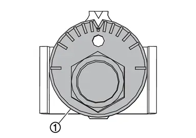
Adjust with adjusting bolt  in front lower link.
| Camber | Refer to Wheel Alignment. |
CAUTION:
-
When tightening the nut firmly and checking the torque, use a wrench to prevent the turning of bolt.
-
After adjusting camber, be sure to check toe-in.
-
After adjusting camber, be sure to perform the height sensor calibration. Refer to Work Support.
-
If camber is not still within the specification, inspect and replace any damaged or worn suspension parts.
TOE-IN
Adjust with adjusting bolt in rear lower link.
| Toe-In | Refer to Wheel Alignment. |
CAUTION:
-
Be sure to adjust equally on right and left side with adjusting bolt.
-
When tightening the nut firmly and checking the torque, use a wrench to prevent the turning of bolt.
-
After adjusting toe-in, be sure to perform the height sensor calibration. Refer to Work Support.
-
If toe-in is not still within the specification, inspect and replace any damaged or worn suspension parts.
Other materials
Oil Pan
Exploded View
A/T assembly
Oil pan gasket
Overflow tube
O-ring
Oil pan
Drain plug
O-ring
O-ring
Refer to Removal and Installation.
: Always replace after every disassembly.
: Apply ATF
Removal and Installation
WARNING: ...
Low Tire Pressure Location Indicator Does Not Display
Description
When low tire pressure, low tire location indicator does not display though low tire pressure warning lamp turns ON.
Diagnosis Procedure
CHECK COMBINATION METER
Check combination meter. Refer to Work flow.
Is the inspection result normal?
YES>>
GO TO 2.
NO>>
Repair or repla ...
Rear Washer Nozzle and Tube
Exploded View
Rear washer nozzle
Rear washer nozzle tube
Connector
Rear washer tube C
Grommet
Connector
Rear washer tube B assembly*1
Rear washer tube A
Tube protector
Washer tank assembly
Intelligent rear view mirror harness B assembly*2
: Clip
...