Exploded View
WITHOUT DYNAMIC DIGITAL SUSPENSION AND ELECTRONIC AIR SUSPENSION
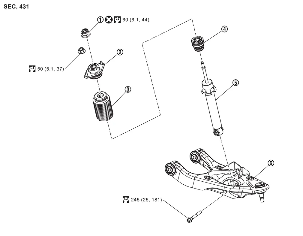
 |
Piston rod lock nut |  |
Shock absorber mounting bracket |  |
Dust cover |
 |
Bound bumper |  |
Shock absorber |  |
Front lower link |
 |
: Always replace after every disassembly. | ||||
 |
: N·m (kg-m, ft-lb) | ||||
WITH DYNAMIC DIGITAL SUSPENSION AND ELECTRONIC AIR SUSPENSION
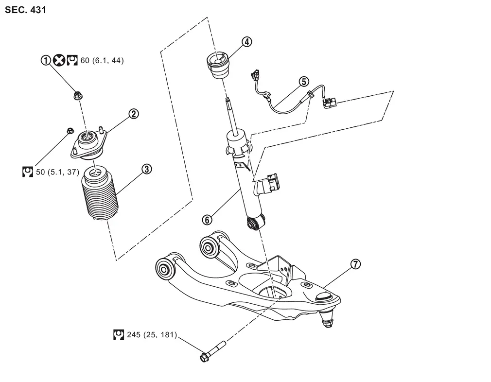
|
Piston rod lock nut | |
Shock absorber mounting bracket | |
Dust cover |
|
Bound bumper | |
Shock absorber harness | |
Shock absorber |
 |
Front lower link | ||||
|
: Always replace after every disassembly. | ||||
|
: N·m (kg-m, ft-lb) | ||||
Removal and Installation
REMOVAL
Without Dynamic Digital Suspension and Electronic Air Suspension
Remove tires. Refer to ROAD WHEEL TIRE : Removal & Installation.
Remove cylinder body. Hang cylinder body in a place where it will not interfere with work. Refer to Removal and Installation.
CAUTION:
Never depress brake pedal while brake caliper is removed.
Loosen front lower link mounting nuts (frame side).
Loosen rear lower link mounting nuts (frame side).
Remove stabilizer clamp. Refer to Removal and Installation.
Remove shock absorber mounting bolt (lower side).
Set suitable jack under axle housing.
CAUTION:
-
Check the stable condition when using a suitable jack.
-
Never damage axle housing.
Remove shock absorber mounting nuts (upper side)
Lower suitable jack.
Lower axle housing, and remove shock absorber from front lower link.
Perform inspection after removal. Refer to Inspection.
With Dynamic Digital Suspension and Electronic Air Suspension
WARNING:
-
When removing the air suspension component parts, always follow the removing procedure since the vehicle height may accidentally drop and it can lead to personal injury.
CAUTION:
Start engine.
Turn auto height mode control switch to ON, shift the shift position to N and set to normal height.
Turn OFF the electronic air suspension function. Refer to Operation.
Stop engine.
Lift up the vehicle.
Remove rear tire. Refer to ROAD WHEEL TIRE : Removal & Installation.
Remove wheel sensor and harness from lower link. Refer to Removal and Installation.
Disconnect shock absorber harness connector.
Support the rear lower link with suitable jack (A) until most horizontal angle with vehicle on the ground.
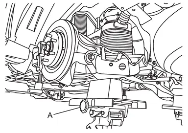
CAUTION:
-
Never damage rear lower link.
-
Check the stable condition when using a suitable jack.
-
Never lower the suitable jack until installation is completed.
Loosen the air connector and perform air bleeding.
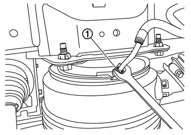
CAUTION:
-
Be careful since air flows swiftly from air tube.
-
Loosen the air connector slowly.
-
Never disconnect the air connector until the air completely bleeds.
Remove air tube together with air connector from air spring .
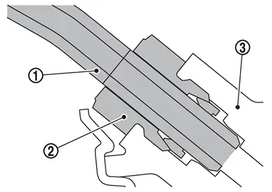
CAUTION:
-
Never damage air connector, air adapter, and air tube.
-
When reusing air connector, never remove air tube from air connector.
-
If you remove the air tube from the air connector, be sure to replace the air connector.
-
Seal remove part using vinyl tape for preventing dirt from getting the remove part.
 NOTE:
NOTE:
The air connector can be reused as long as you never remove air tube from air connector.
Remove cylinder body. Hang cylinder body in a place where it will not interfere with work. Refer to Removal and Installation.
CAUTION:
Never depress brake pedal while brake caliper is removed.
Remove stabilizer clamp. Refer to Removal and Installation.
Loosen front lower link mounting nuts (frame side). Refer to Removal and Installation.
Loosen rear lower link mounting nuts (frame side). Refer to Removal and Installation.
Separate rear lower link from axle housing. Refer to Removal and Installation.
Remove shock absorber mounting bolt (lower side).
Set suitable jack under axle housing.
CAUTION:
-
Never damage axle housing.
-
Check the stable condition when using a suitable jack.
Remove shock absorber mounting nuts (upper side)
Lower suitable jack.
Lower axle housing, and remove shock absorber from front lower link.
Perform inspection after removal. Refer to Inspection.
INSTALLATION
Without Dynamic Digital Suspension and Electronic Air Suspension
Note the following, and install in the reverse order of removal.
-
Perform final tighting of shock absorber (lower side) by the following procedures.
-
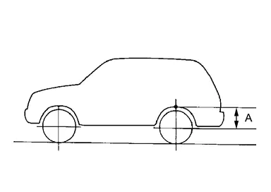
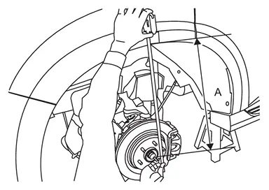
Measure between wheel center and fender arch (A).
NOTE:
Note the measurements.
-
Set the wheel chocks on the front tires.
-
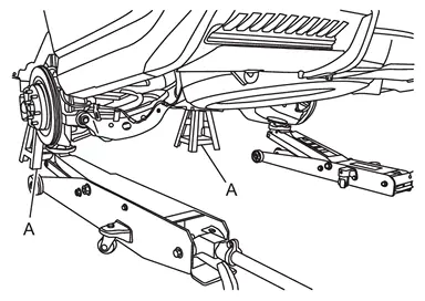
Jack up the rear of the vehicle and set the rigid rack.
-
Remove the rear tires.
-
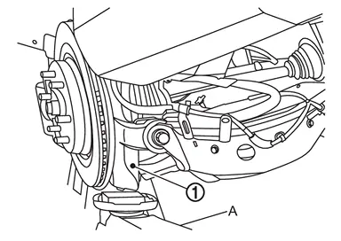
Set suitable jacks (A) on the left and right axle housings
. (axle housing ball joint fastening part).CAUTION:
Never damage threaded part of ball joint.
-
Jack up the left and right axle housings until the vehicle no longer floats off the rigid rack (A).
CAUTION:
-
Never damage axle housings.
-
Check the stable condition when using a suitable jack.
-
Never float the vehicle.
NOTE:
Jack up left and right at the same time.
-
-
Measure between wheel center and fender arch (A).
CAUTION:
-
Check the measurements are within +20 mm (0.79 in) from step 1.
-
If the measurements are +20 mm (0.79 in) or more, perform step 6 again.
-
-
Tight the mounting bolt of shock absorber (lower side) to the specified torque. Refer to Exploded View.
-
-
Perform inspection after installation. Refer to Inspection.
-
After replacing the shock absorber, always follow the disposal procedure to discard the shock absorber. Refer to Disposal.
With Dynamic Digital Suspension and Electronic Air Suspension
Install shock absorber.
Install rear lower link to axle housing. Refer to Removal and Installation.
CAUTION:
Never reuse mounting nut.
Tighten rear lower link mounting nuts (frame side). Refer to Removal and Installation.
CAUTION:
Never reuse mounting nut.
Tighten front lower link mounting nuts (frame side). Refer to Removal and Installation.
CAUTION:
Never reuse mounting nut.
Install stabilizer clamp. Refer to Removal and Installation.
Install cylinder body. Refer to Removal and Installation.
Install air tube and air connector together to air spring .
CAUTION:
-
Never damage air connector and air tube.
-
If you remove the air tube from the air connector, be sure to replace the air connector.
-
Never let foreign materials entered into parts.
Start engine.
Use CONSULT and fill the inner pressure of air spring to 3.3 bar. Refer to Work Support.
Remove suitable jack from rear lower link.
Use CONSULT and fill the inner pressure of air spring to 3.3 bar. Refer to Work Support.
Install shock absorber harness connector.
CAUTION:
Never twist or pull shock absorber harness, when installing.
Stop engine.
Install tire. Refer to ROAD WHEEL TIRE : Removal & Installation.
Lift down the vehicle.
Start engine.
Perform pressure measurements using CONSULT. Refer to Work Support.
NOTE:
Confirm that "Air suspension internal pressure judgement" is OK.
Perform the height sensor calibration using CONSULT. Refer to Work Support.
Use CONSULT and vehicle to the normal height. Refer to Work Support.
Turn ON the electronic air suspension function. Refer to Operation.
Stop engine.
Perform final tighting of front lower link (frame side) by the following procedures.Measure between wheel center and fender arch (A).
NOTE:
Note the measurements.
.
CAUTION:
Never damage threaded part of ball joint.
CAUTION:
-
Never damage axle housings.
-
Check the stable condition when using a suitable jack.
-
Never float the vehicle.
NOTE:
Jack up left and right at the same time.
CAUTION:
-
Check the measurements are within +20 mm (0.79 in) from step a.
-
If the measurements are +20 mm (0.79 in) or more, perform step f again.
Perform inspection after installation. Refer to Inspection.
After replacing the shock absorber, always follow the disposal procedure to discard the shock absorber. Refer to Disposal.
Disassembly and Assembly
DISASSEMBLY
CAUTION:
-
Never damage shock absorber piston rod when removing components from shock absorber.
-
When fixing shock absorber with a vise, wrap a shop cloth around lower side of shock absorber to protect from damage. Never set the cylindrical part of shock absorber with a vise.
-
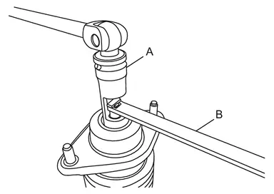
When removing the shock absorber mounting bracket, use the rear shock absorber service kit [SST: KV401110S0 ( ― ) ] to hold the shock absorber rod. A: Soket 18 :[SST: KV40111000(NI-53363)] B: Rod lock handle :[SST: KV40111100(NI-53362)]
ASSEMBLY
CAUTION:
-
Never damage shock absorber piston rod when removing components from shock absorber.
-
When fixing shock absorber with a vise, wrap a shop cloth around lower side of shock absorber to protect from damage. Never set the cylindrical part of shock absorber with a vise.
-
When assembling dust cover, bound bumper, and shock absorber mounting bracket, follow the procedure below.
-
Install bound bumper
to dust cover .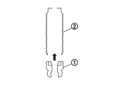
-
Install dust cover
and bound bumper to shock absorber mounting bracket .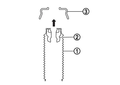
-
Install shock absorber to bound bumper, dust cover, and shock absorber mounting bracket.
NOTE:
Check that part
 of dust cover is attached to shock absorber .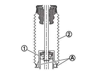
-
-
When installing the shock absorber mounting bracket, use the rear shock absorber service kit [SST: KV401110S0 ( ― ) ] to hold the shock absorber rod. A: Soket 18 :[SST: KV40111000(NI-53363)] B: Rod lock handle :[SST: KV40111100(NI-53362)]
CAUTION:
Never reuse piston rod lock nut.
Inspection
INSPECTION AFTER REMOVAL
Check the following items, and replace the parts if necessary.
-
Shock absorber assembly for deformation, cracks, damage.
-
Piston rod on shock absorber assembly for damage, uneven wear, and distortion.
-
Welded and sealed areas for oil leakage.
INSPECTION AFTER INSTALLATION
Without Dynamic Digital Suspension and Electronic Air Suspension
Check wheel alignment. Refer to Inspection.
With Dynamic Digital Suspension and Electronic Air Suspension
-
Make sure the electronic air suspension function is turn ON. Refer to Operation.
-
Confirm that no warning message is displayed on the information display. Refer to Air suspension warning.
-
Perform the self-diagnosis with CONSULT. Check if any DTC is detected. Refer to CONSULT Function.
-
Confirm to close the hood.
-
Always check for the air leakage with soapy water.
-
Check wheel alignment. Refer to Inspection.
Disposal
-
Set shock absorber horizontally with the piston rod fully extended.
-
Drill 2 – 3 mm (0.08 – 0.12 in) hole at the position (
 ) from top as shown in the figure to release gas gradually.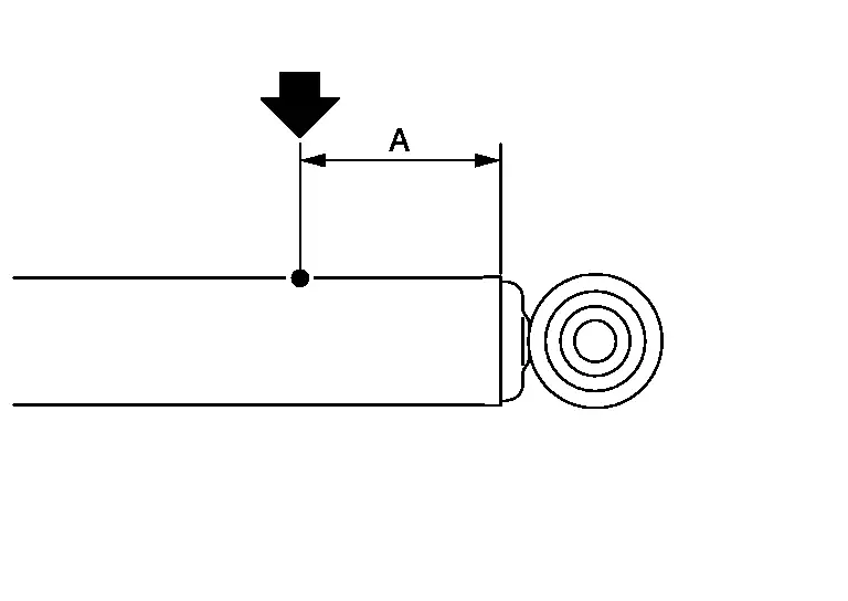
CAUTION:
-
Wear eye protection (safety glasses).
-
Wear gloves.
-
Be careful with metal chips or oil blown out by the compressed gas.
NOTE:
-
Drill vertically in this direction (
 ).
). -
Directly to the outer tube avoiding brackets.
-
The gas is clear, colorless, odorless, and harmless.
A : 20 – 30 mm (0.79 – 1.18 in) -
-
Position the drilled hole downward and drain oil by moving the piston rod several times.
CAUTION:
Dispose of drained oil according to the law and local regulations.
Other materials
Second Seatback
Disassembly and Assembly
CAUTION:
When disassemble, always use a remover tool that is made of plastic to prevent damage.DISASSEMBLYRemove inside and outside seat cushion finisher outer. Refer to Disassembly and Assembly.
Remove armrest (LH seat).Disengage fixing pawls using a remover tool (A), and t ...
All Component
Diagnosis Procedure
CHECK MANUAL OPERATION
Check manual operation.
Does it operate normally?
YES>>
GO TO 2.
NO>>
Repair or replace the malfunctioning parts.
PERFORM MEMORY STORING
Perform MEMORY STORING. Refer to Description.
Check memory function operation.
Does it operate norma ...
Precautions
Precaution for Supplemental Restraint System (SRS) "AIR BAG" and "SEAT BELT PRE-TENSIONER"
The Supplemental Restraint System such as “AIR BAG” and “SEAT BELT PRE-TENSIONER”, used along with a front seat belt, helps to reduce the risk or severity of injury to the driver and front passenger fo ...