
Nissan Armada 2025-2026 Service and Repair Manual: Work Flow
OVERALL SEQUENCE
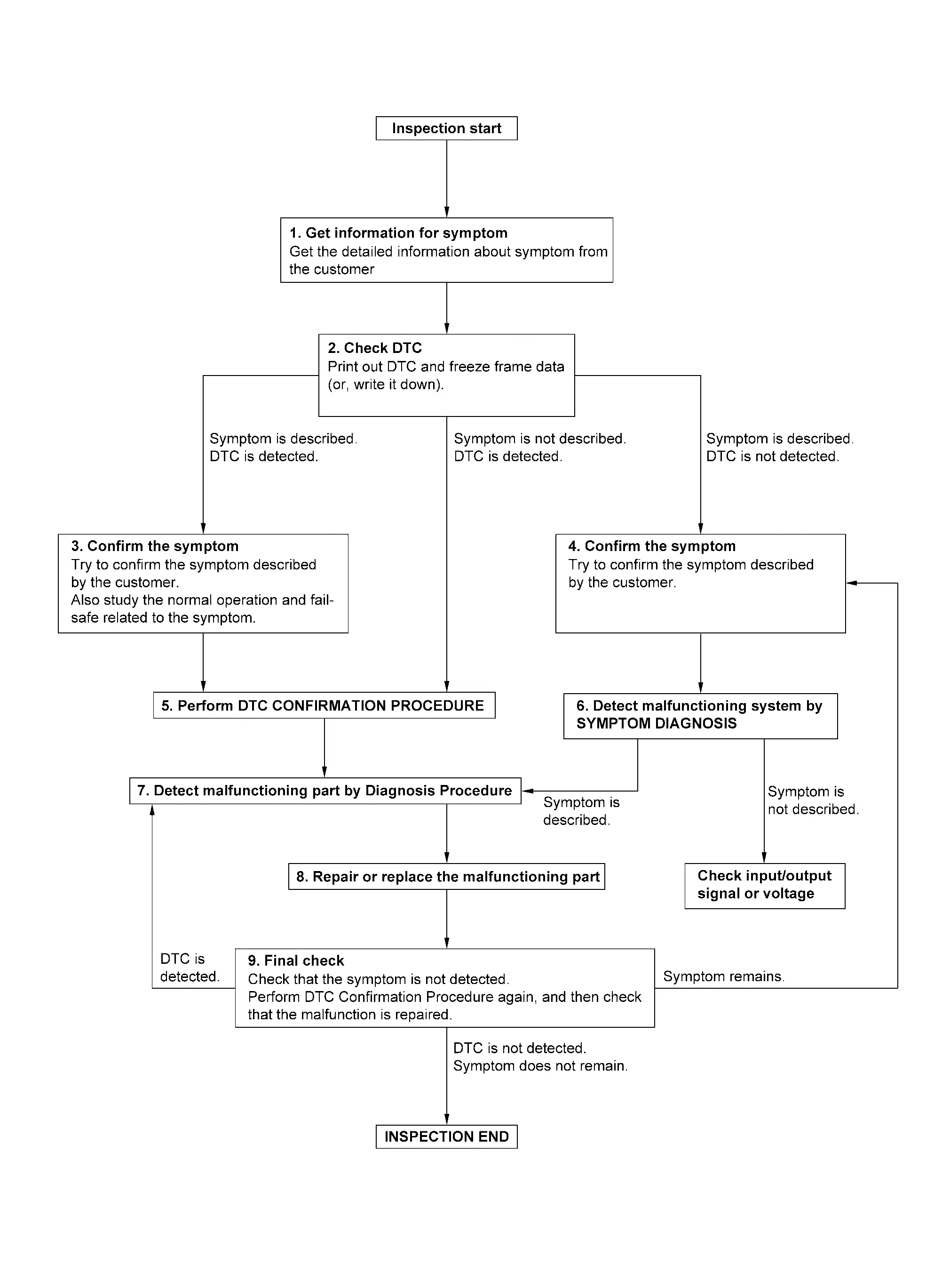
DETAILED FLOW
GET INFORMATION FOR SYMPTOM
Check operation condition of the function that is malfunctioning.
GO TO 2.
CHECK DTC
Check DTC.
Perform the following procedure if DTC is detected.
Record DTC and freeze frame data (Print them out using CONSULT.)
Erase DTC.
Are any symptoms described and any DTC detected?
Symptom is described, DTC is detected>>GO TO 3.
Symptom is described, DTC is not detected>>GO TO 4.
Symptom is not described, DTC is detected>>GO TO 5.
CONFIRM THE SYMPTOM
Try to confirm the symptom described by the customer.
Also study the normal operation and fail-safe related to the symptom.
>>GO TO 5.
CONFIRM THE SYMPTOM
Try to confirm the symptom described by the customer.
>>GO TO 6.
PERFORM DTC CONFIRMATION PROCEDURE
 NOTE:
NOTE:
Freeze frame data is useful if the DTC is not detected.
Is DTC detected?
YES>>GO TO 7.
NO>>Check according to Intermittent Incident.
DETECT MALFUNCTIONING SYSTEM BY SYMPTOM DIAGNOSIS
Is the symptom described?
YES>>GO TO 7.
NO>>DETECT MALFUNCTIONING PART BY DIAGNOSIS PROCEDURE
Inspect according to Diagnosis Procedure of the system.
Is malfunctioning part detected?
YES>>GO TO 8.
NO>>Check according to Intermittent Incident.
REPAIR OR REPLACE THE MALFUNCTIONING PART
Repair or replace the malfunctioning part.
Check DTC. If DTC is detected, erase it.
GO TO 9.
FINAL CHECK
Is DTC detected and does symptom remain?
YES-1>>DTC is detected: GO TO 7.
YES-2>>Symptom remains: GO TO 4.
NO>>Before returning the vehicle to the customer, always erase DTC.


Other materials:
STEERING ASSIST SWITCH : Removal & Installation
REMOVAL
Remove instrument pad A. Refer to Removal and Installation.
Remove mounting screws , and remove switch panel from instrument pad A .
Unhook the pawls to remove the switch from the switch panel . 
INSTALLATION
Installation is in the reverse order of removal. ...
Inspection
WARNING:
LOOSENESS OF CONNECTED PART
Check each fixing bolt and nut for looseness using torque wrench. For each tightening torque, refer to Exploded View.
BACKLASH OF JOINT PART
BACKLASH OF CENTER BEARING
Move the shaft near center bearing up and down and from side to side (axial direction of shaft ...
Work Procedure
WARNING:
REPLACE A/T ASSEMBLY
Replace A/T assembly. Refer to Removal and Installation (2WD) or Removal and Installation (4WD).
>>
GO TO 2.
WRITING Vehicle SPECIFICATIONS
With CONSULT
Ignition switch ON.
Select "TRANSMISSION".
Select "Replace ECU".
Perform the work according to the procedure ...

0.0054