
Nissan Armada 2025-2026 Service and Repair Manual: Work Procedure
Perform camera calibration and perform writing to the around view monitor control unit, after removal/installation or replacement of each camera or camera mounting parts (front bumper molding center, door mirror, or others), or replacement of around view monitor control unit.
| Parts name | Operation | Operation | |
| Replacement | Removal | ||
| Front camera | x | x | Camera calibration |
| Front bumper molding center | x | x | |
| Side camera | x | x | |
| Door mirror ASSY | x | x | |
| Rear camera | x | x | |
| Back door ASSY | x | x | |
 NOTE:
NOTE:
When replace the around view monitor C/U, memorized calibration data in each camera are written in around view monitor C/U by using work support "Camera calibration". Calibration by using targets is not necessary.
PREPARATION
PERFORM SELF-DIAGNOSIS
Perform self diagnosis of AROUND VIEW MONITOR using CONSULT.
Is DTC detected?
YES-1>>Detecting DTC other than B2A04-51: Perform a corresponding diagnosis from the DTC list first. Refer to DTC Index.
YES-2>>Detected DTC B2A04-51. GO TO 2.
NO>>GO TO 3.
CHECK REPLACED PARTS
Check replaced parts.
NOTE:
When replace only around view monitor C/U, each camera memorizes calibration data, calibration by installing the target is unnecessary.
Is only around view monitor C/U replaced?
YES>>Select "Work support", "CALIBRATING CAMERA IMAGE" and write camera calibration data.
NO>>GO TO 3.
CAMERA CALIBRATION PREPARATION
Check tire pressure and adjust to regular pressure.
Vehicle in no-load condition.
Empty the vehicle.
Select shift position P and release parking brake.
Open door mirror.
Clean each cameras.
Secure work space for calibration according to the camera.
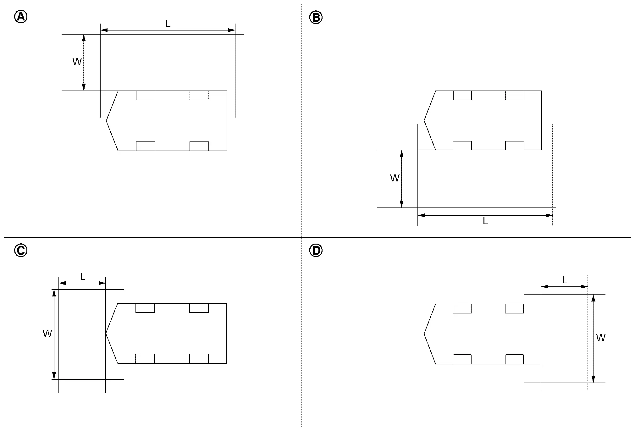

Driver camera calibration
L: 5000 mm
W: 3000 mm
Passenger side camera calibration
L: 5000 mm
W: 3000 mm
Front camera calibration
L: 3000 mm
W: 5000 mm
Rear camera calibration
L: 3000 mm
W: 5000 mm
GO TO 4.
PREPARATION OF CALIBRATION TARGET
Prepare fourteen sheets of white paper and black paper, respectively, with dimensions of 200 mm (7.87 in) X 200 mm (7.87 in) to create a left target and right target.
Tape two sheets of black paper and two sheets of white paper together to make a target of 400 mm (15.75 in) X 400 mm (15.75 in).
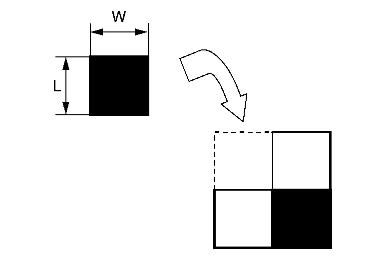
L : 200 mm W : 200 mm NOTE:Use a transparent tape.
Following step 2, create 6 targets (7 targets required).
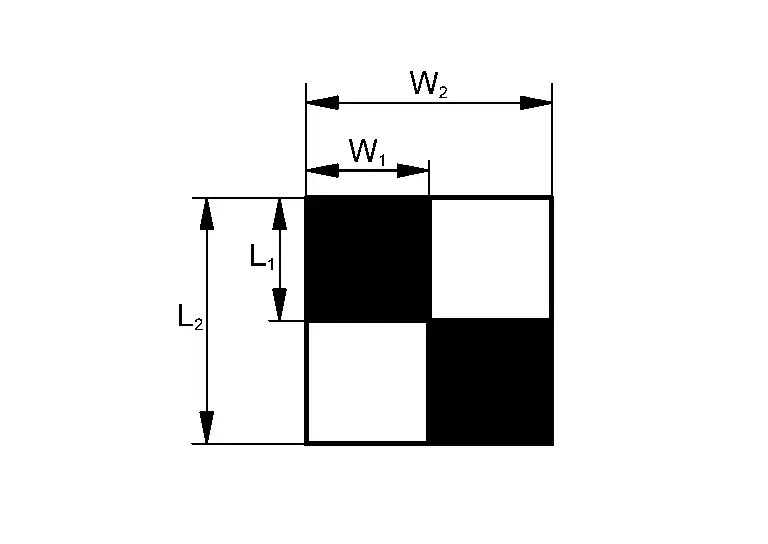
L1 : 200 mm L2 : 400 mm W1 : 200 mm W2 : 400 mm NOTE:Never apply tape to target surface.
Never allow a clearance on the black and white boundary.
GO TO PERFORM CALIBRATION
PERFORM CALIBRATION
AXLE CENTER MEASUREMENT
Prepare laser leveler (KV 991 20 000).
Turn ON.
NOTE:When move laser leveler, turn OFF.
Check air bubbles and adjust the level of laser leveler.
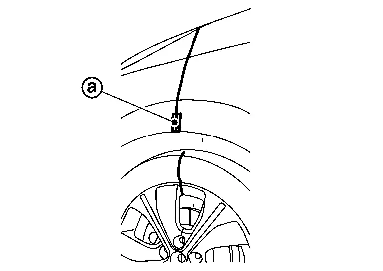
Irradiate laser
vertically to become through center of front wheel hub.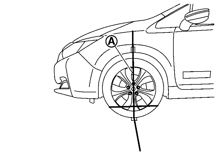
Laser Apply masking tape on front fender, and put a mark on laser
 .
.
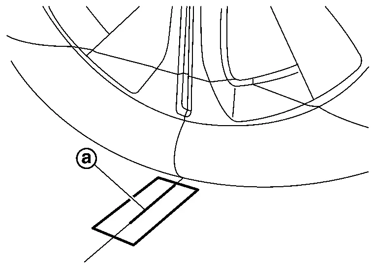
Apply tape on the ground, and make a line along with laser
.
Move laser leveler 45 degrees
as shown in the figure.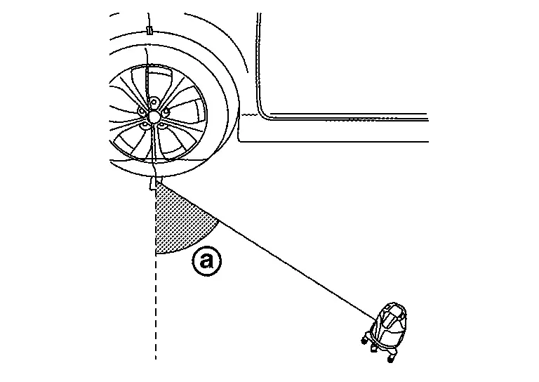
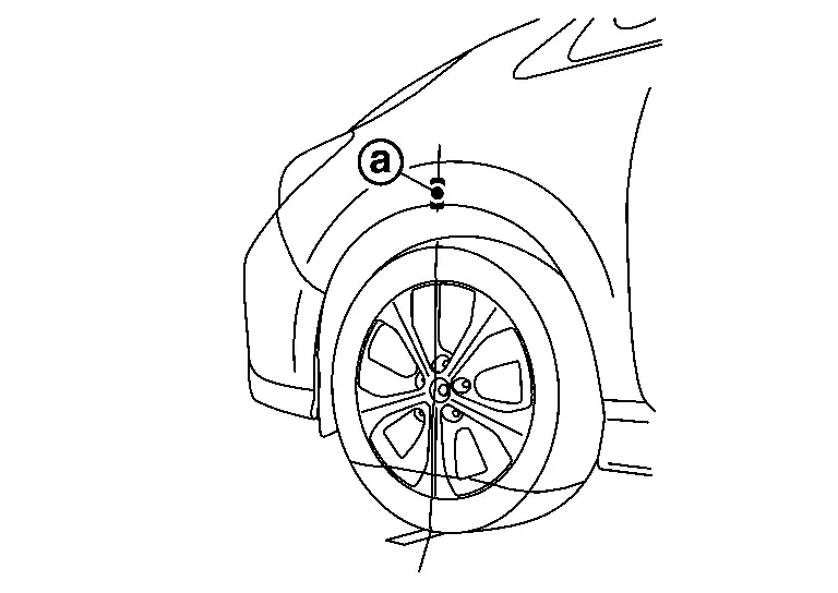
Align the laser beam irradiation position through the marked position on the fender
.
Draw a line
 along the laser light irradiation line through the tape attached to the ground.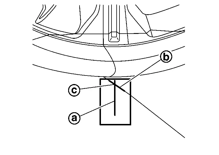
Make sure there are two lines
and crossing on the tape attached on the ground. The point  where the lines on the tape intersect is the axle center point vertically lowered from the fender.
Perform same operation for remaining three axle center position.
GO TO 2.
CHECK CAMERA
Check the camera to be calibrated.
Left side camera or right side camera.>>GO TO 3.
Front or rear camera.>>GO TO 4.
PREPARATION OF AIMING ADJUSTMENT JIG (Driver side or passenger side)
Mark the position of 500 mm (19.69 in) (L) from the center point of the front axle.
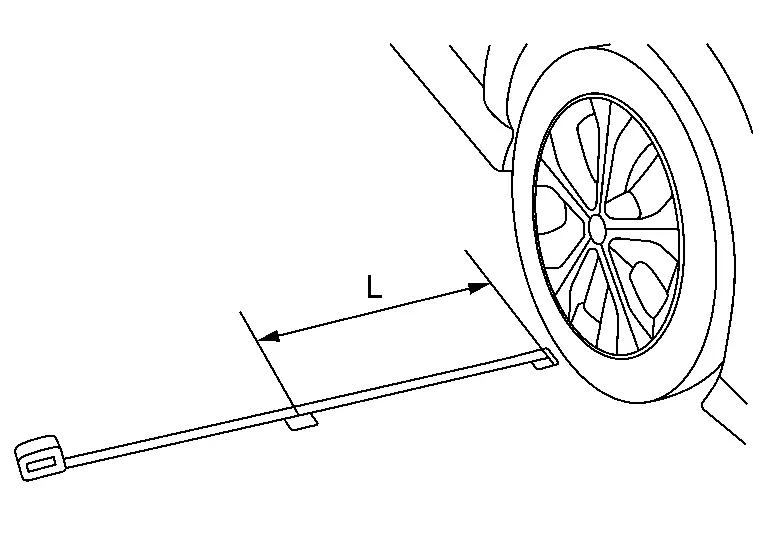
Perform same operation for rear side. Mark the position of 500 mm (19.69 in) (L) from the center point of the rear axle.
Extend the measure 4000 mm (157.48 in) and install it so that it passes the marked position on the front and rear side.
Adjust the position of measure (A) so that the marking position of 500 mm (19.69 in) from the center point of the front axle is 1000 mm (39.37 in) (L2) from the end.
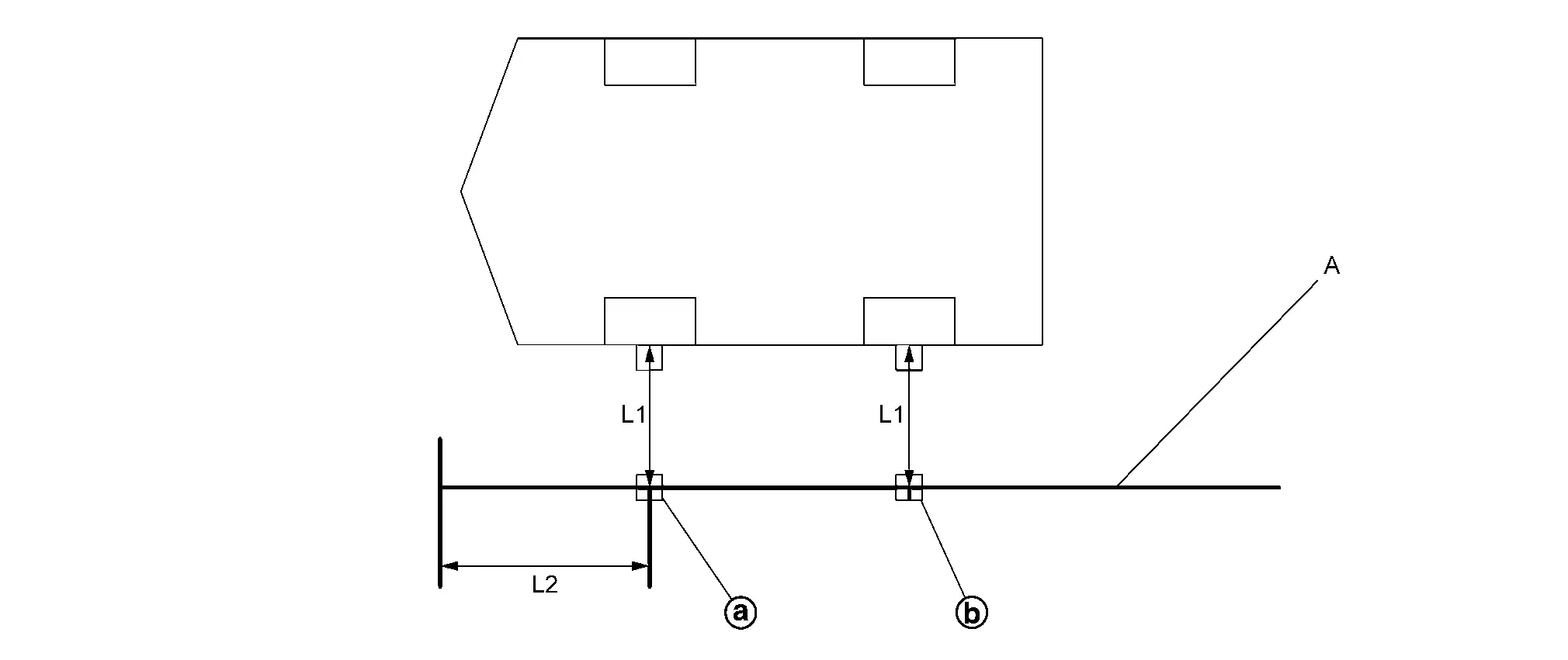
Front marking position Rear marking positon L1 : 500 mm (19.69 in) L2 1000 mm (39.37 in) A Measure Set the target center on measure (A) position 1000 mm (39.37 in). One of the black part of target must be located on left depth side from camera.
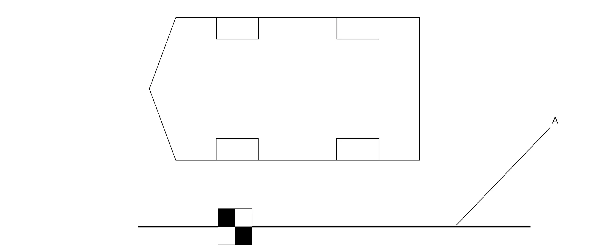
A Measure Set the target center on measure (A) position 0 mm. One of the black part of target must be located on left depth side from camera.
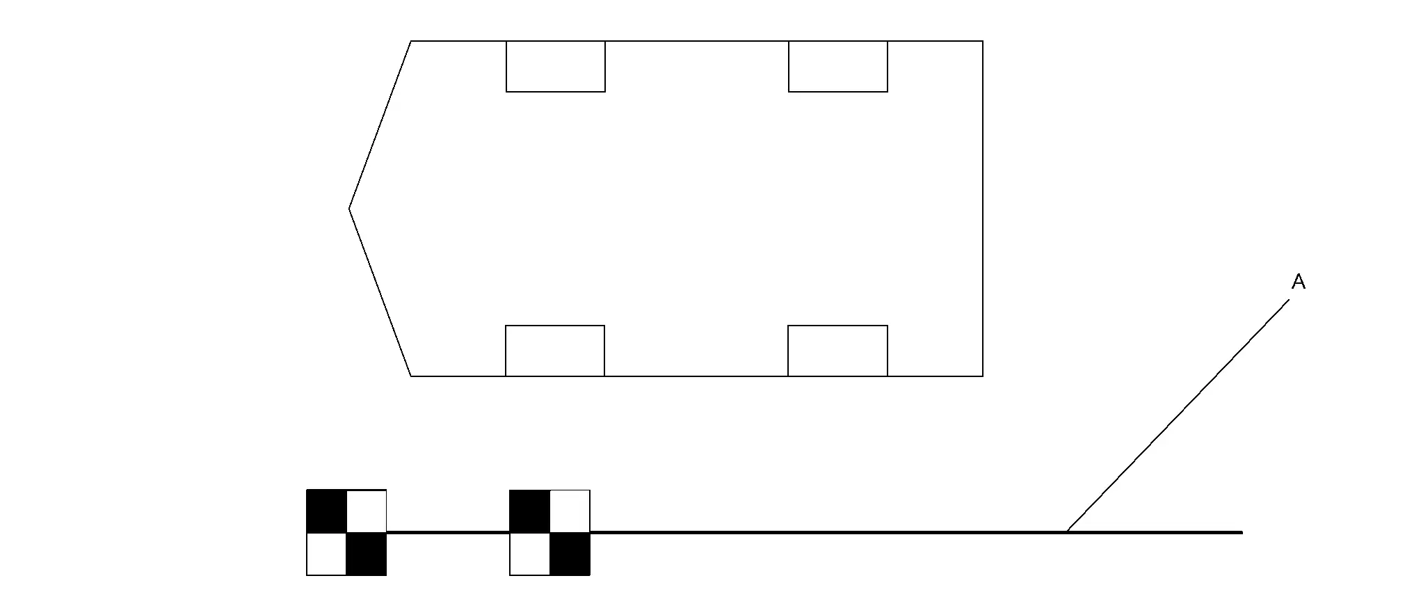
A Measure Set the remaining three targets at the interval of 1000 mm (39.37 in). One of the black part of target must be located on left depth side from camera.
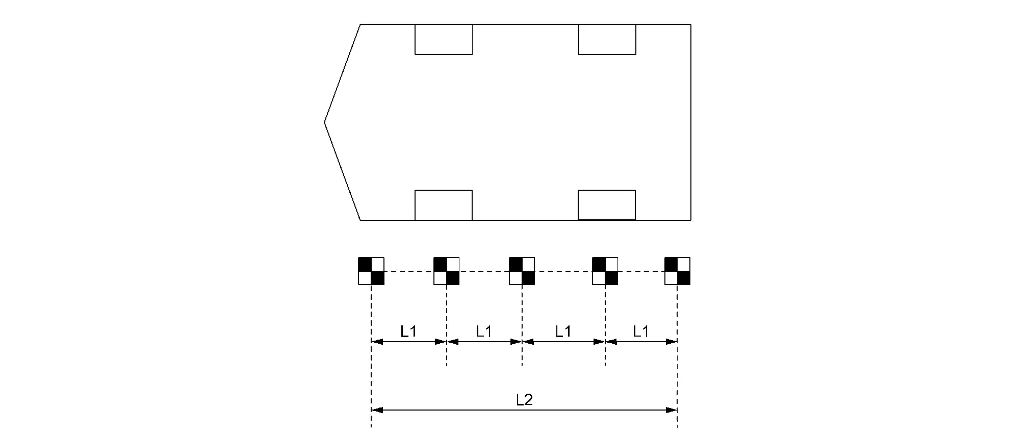
L1 : 1000 mm (39.37 in) (tolerance ± 10 mm (0.39 in)) L2 : 4000 mm (157.48 in) (tolerance ± 10 mm (0.39 in)) Set the target on the position 2000 mm (78.74 in) from the front and rear end of target. One of the black part of target must be located on left depth side from camera.
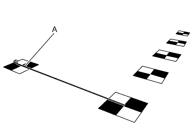
A : Measure Move the target approx 45 degrees so that the black part of target be located on left depth side from camera.
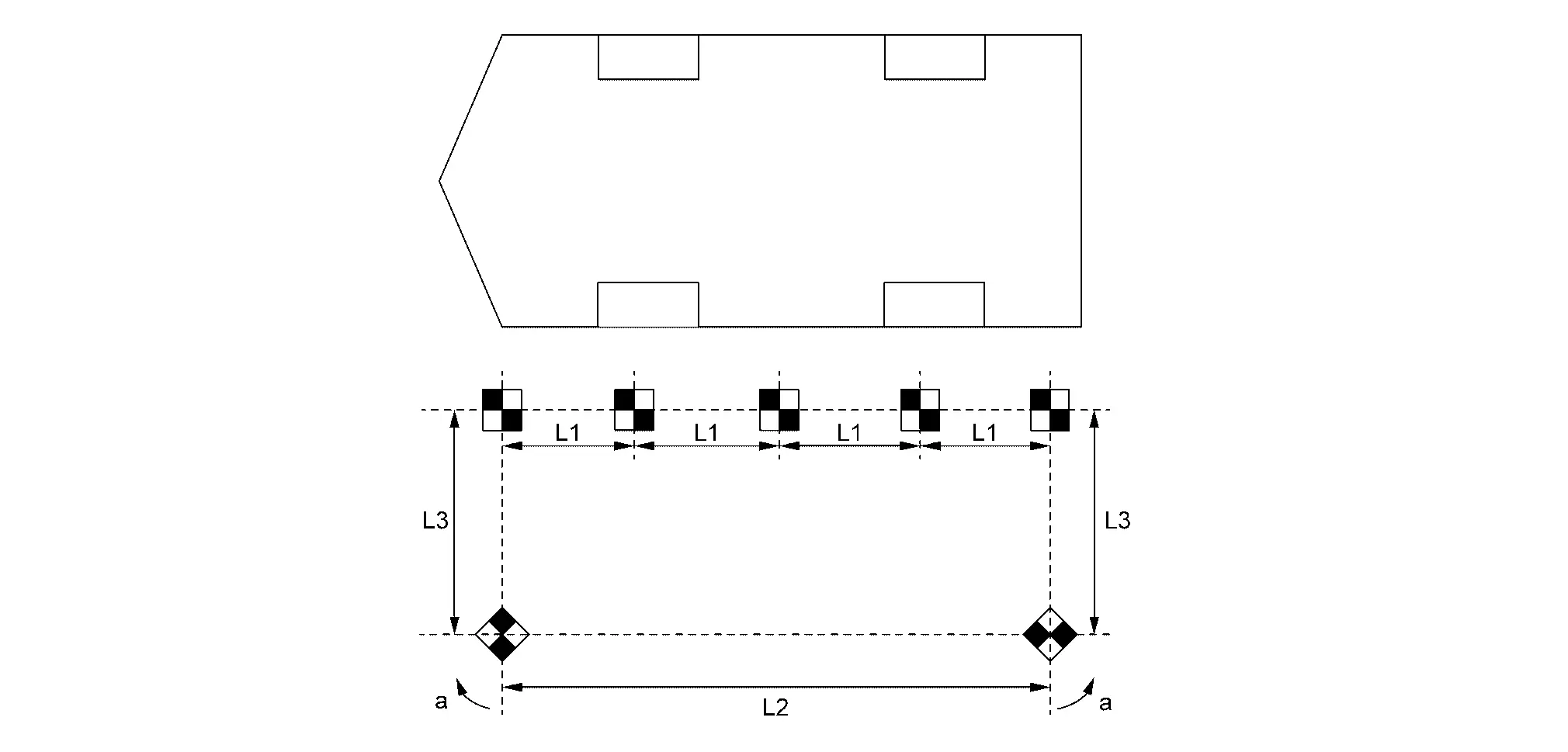
L1 : 1000 mm (39.37 in) (tolerance ± 10 mm (0.39 in)) L2 4000 mm (157.48 in) (tolerance ± 10 mm (0.39 in)) L3 : 2000 mm (78.74 in) (tolerance ± 10 mm (0.39 in)) a : approx. 45 degrees
GO TO 5.
PREPARATION OF AIMING ADJUSTMENT JIG (Front or Rear)
Prepare laser leveler (KV 991 20 000).
Turn ON.
NOTE:When move laser leveler, turn OFF.
Check air bubbles and adjust the level of laser leveler.
Irradiate laser
in the vertical direction to through the center part of the front emblem.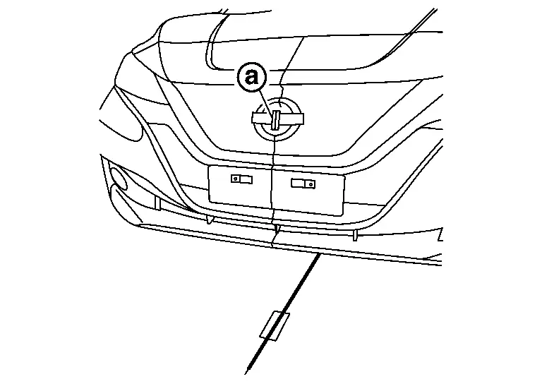
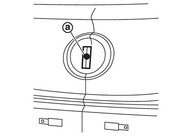
Apply masking tape on front emblem, and put a mark on laser line
.
Draw a line
along the laser light irradiation line through the tape attached to the ground.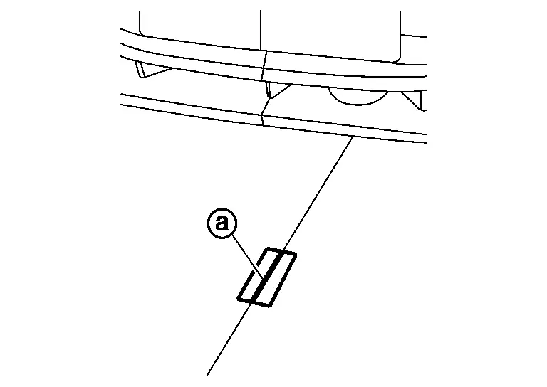 NOTE:
NOTE:Put a tape under the front emblem.
Move laser leveler 45 degrees as shown in the figure.
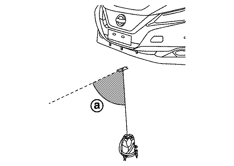
Align the laser beam irradiation position through the marked position on the front emblem
.Draw line
along the laser light irradiation line through the tape attached to the ground.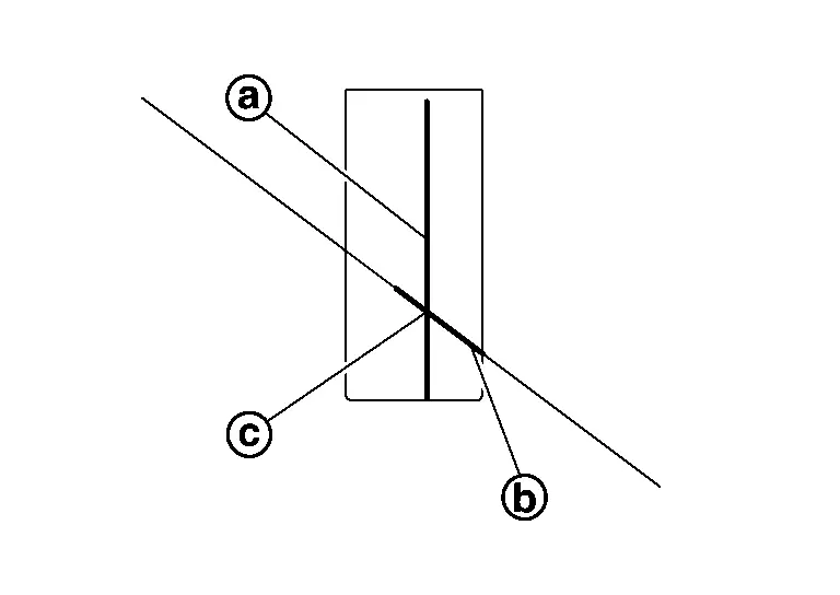
Make sure there are two lines
and crossing on the tape attached on the ground. The point where the lines on the tape intersect is the axle center point vertically lowered from the fender.Perform same operation for rear side.
Extend the measure and install it through the marked position on the front and rear side.
Mark the position
of 500 mm (L) from the front emblem center point.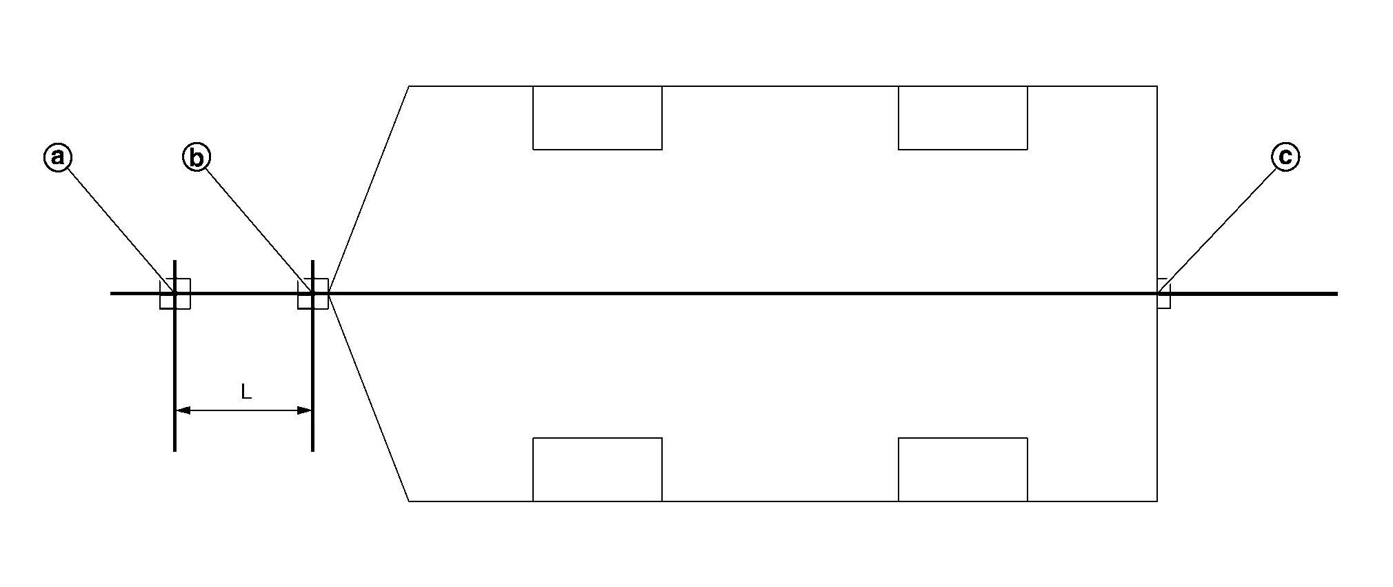
: Position of 500 mm (19.69 in) from front emblem Center position of front emblem : Center position of rear emblem L : 500 mm (19.69 in) Set the target on the position 500 mm (19.69 in) (L) from center of front emblem. One of the black part of target must be located on left depth side from camera.
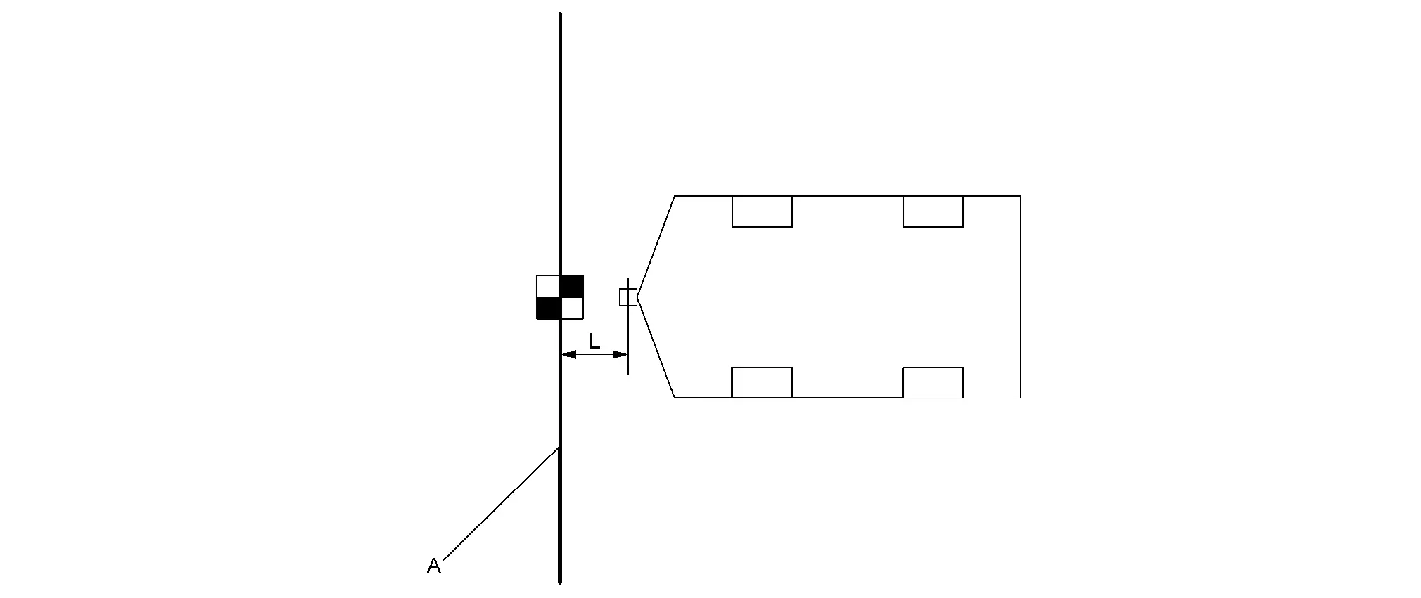
A Measure Set the remaining four targets at the interval of 1000 mm (39.37 in). One of the black part of target must be located on left depth side from camera.
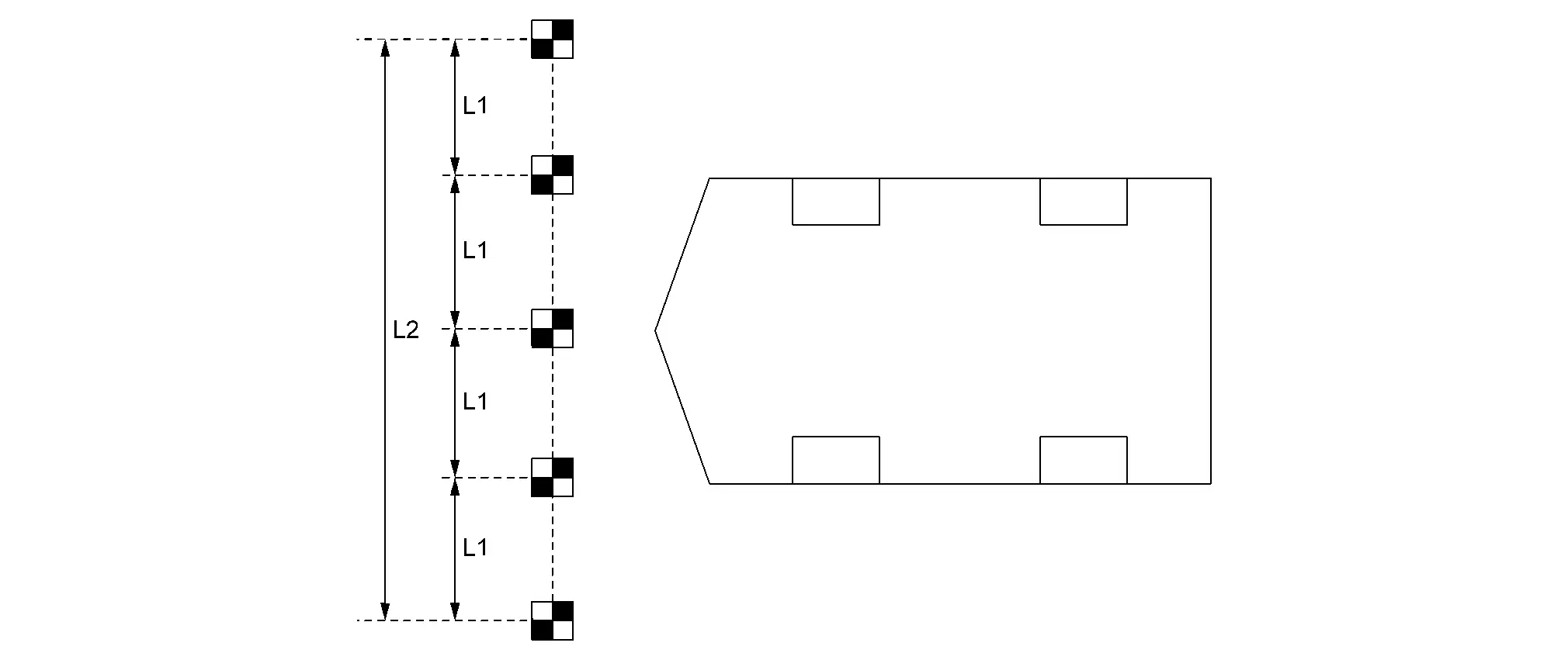
L1 : 1000 mm (39.37 in) (tolerance ± 10 mm (0.39 in)) L2 : 4000 mm (157.48 in) (tolerance ± 10 mm (0.39 in)) Set the target on the position 2000 mm (78.74 in) from the left and right end of target. One of the black part of target must be located on left depth side from camera.
A Measure Move the target approx 45 degrees so that the black part of target be located on left depth side from camera.
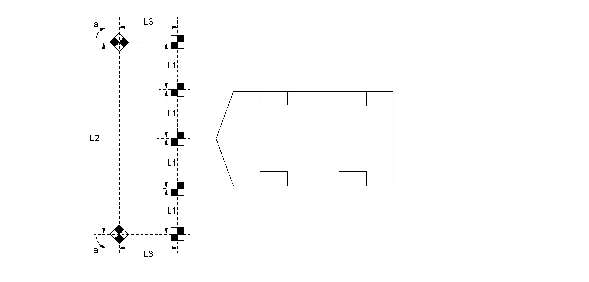
L1 : 1000 mm (39.37 in) (tolerance ± 10 mm (0.39 in)) L2 : 4000 mm (157.48 in) (tolerance ± 10 mm (0.39 in)) L3 : 2000 mm (78.74 in) (tolerance ± 10 mm (0.39 in)) a approx. 45 degrees
GO TO 5.
TARGET RECOGNITION OPERATION
Select "AROUND VIEW MONITOR", "Work support" and �Camera calibration".
Select camera to be calibrated.
NOTE:Loading time of status will be taken one minute.
Status Outline Countermeasure Normal Normal status When remove camera or camera installed parts (front bumper molding, door mirror, or other), calibrate removed camera.
NOTE:The calibration data of before removal is memorized. Therefore, in case of the camera or the part which the camera installed were removed and reinstalled, the status will be displayed as Normal.
When replace only around view monitor, writing of calibration data from the camera is completed Calibration data was written, operation complete Processing Camera is processing a data If the status is not changed, replace corresponding camera and calibrate. Camera disconnected Camera is not connected Check camera connecting condition
If camera connecting condition is proper, replace camera and calibrate
Different version of camera When the camera version recognized by the around view monitor C/U differs from the actual camera version Replace camera and calibrate Calibration data not existing Calibration has not been done Calibrate camera Recognize the target to around view monitor C/U by CONSULT.
NOTE:Perform outside of the vehicle and never move the vehicle.
After recognizing, allowed to enter the vehicle and adjust from inside of the vehicle.
Recognition result is displayed in the navigation display.
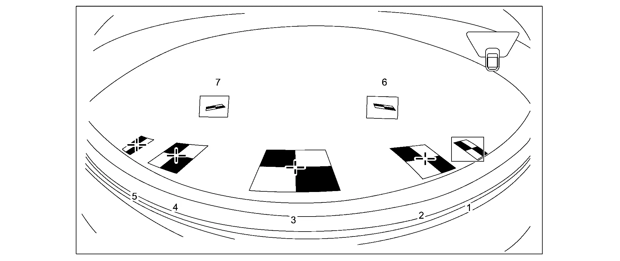 NOTE:
NOTE:In case target T1 - T5 recognized automatically, the cross mark is displayed in the center of target.
In case target T1 - T5 does not recognized automatically, the target is enclosed by blue line frame.
The target T6 and T7 on outside are not recognized automatically.
Touch the number displayed in CONSULT and check all the targets in the enlarged display.
NOTE:Also enlarge the target that was automatically recognized and check that the cross mark is aligned with the center of the target.
Checking the screen of the enlarged target, use the larger arrow button displayed on the CONSULT to adjust the cross mark to approach the target center.
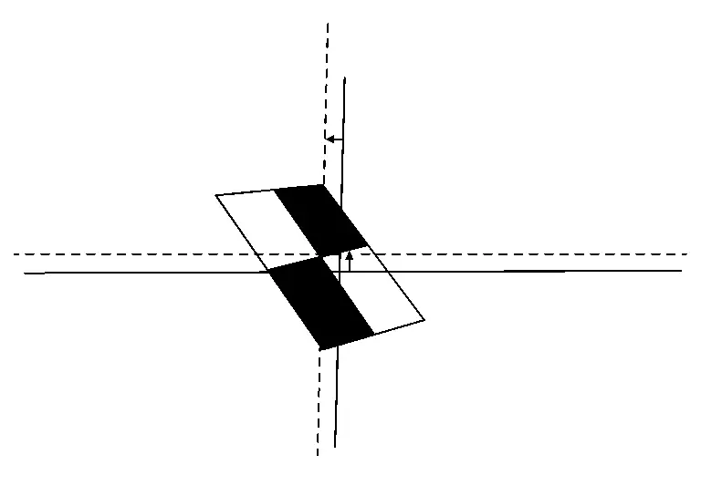
Move the cross line to center using the big arrow button. Adjust the cross line using the small arrow button until it is matched to the center of target.
Also check the enlarged screen for the automatically recognizable target, and adjust it if the cross mark and the target center are not aligned.
Adjust the approximate position with the arrow buttons of the bigger movements and make fine adjustments with the arrow buttons of the smaller movements to easily match the cross mark to the center of the target.
Check the condition of target (checked by check mark) and selected mm unit. And then touch next.
GO TO 6.
TARGET DISTANCE MEASUREMENT
Move the vehicle to the place where do not hinder calibration operation.
NOTE:Do not turn OFF the ignition switch until the calibration operation is completed.
Be careful of the remaining battery power of CONSULT will not turn OFF during the calibration process.
Do not move the targets and axle point marking positions installed during the calibration operation.
Measure the distance from the specified axle center point to the target in the order of L1 to L8.
Driver side camera
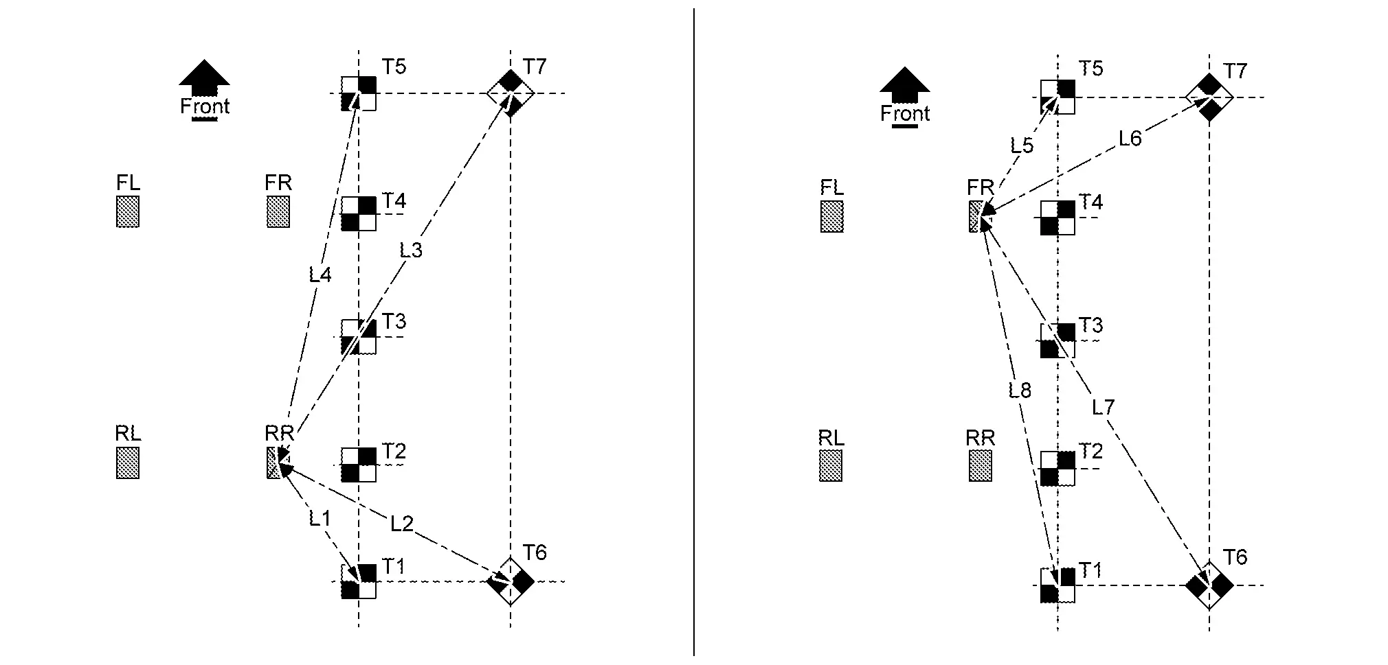
L1 Distance from right rear axle center marking to target T1 L2 Distance from right rear axle center marking to target T6 L3 Distance from right rear axle center marking to target T7 L4 Distance from right rear axle center marking to target T5 L5 Distance from right front axle center marking to target T5 L6 Distance from right front axle center marking to target T7 L7 Distance from right front axle center marking to target T6 L8 Distance from right front axle center marking to target T1 Passenger side camera
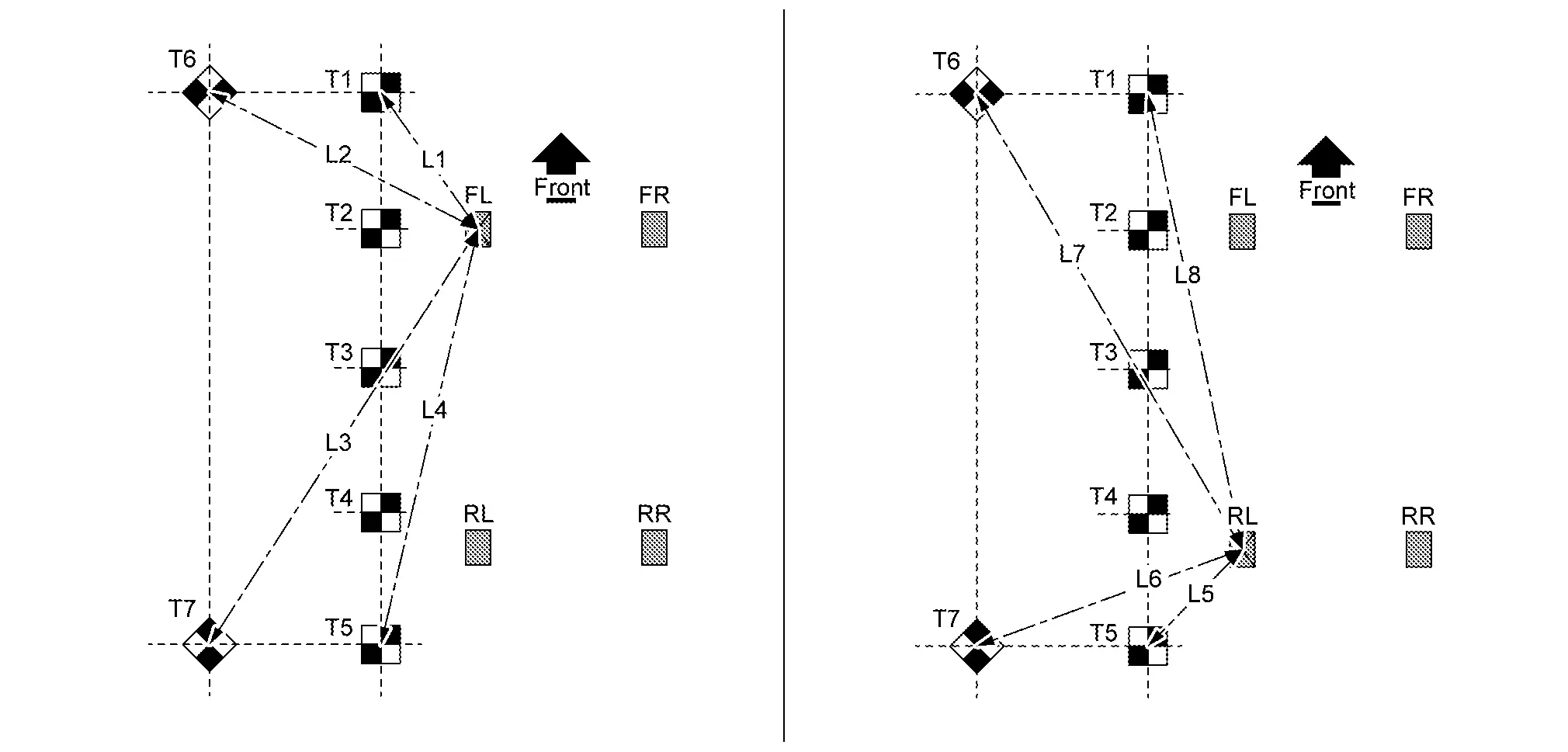
L1 Distance from left front axle center marking to target T1 L2 Distance from left front axle center marking to target T6 L3 Distance from left front axle center marking to target T7 L4 Distance from left front axle center marking to target T5 L5 Distance from left rear axle center marking to target T5 L6 Distance from left rear axle center marking to target T7 L7 Distance from left rear axle center marking to target T6 L8 Distance from left rear axle center marking to target T1 Front camera
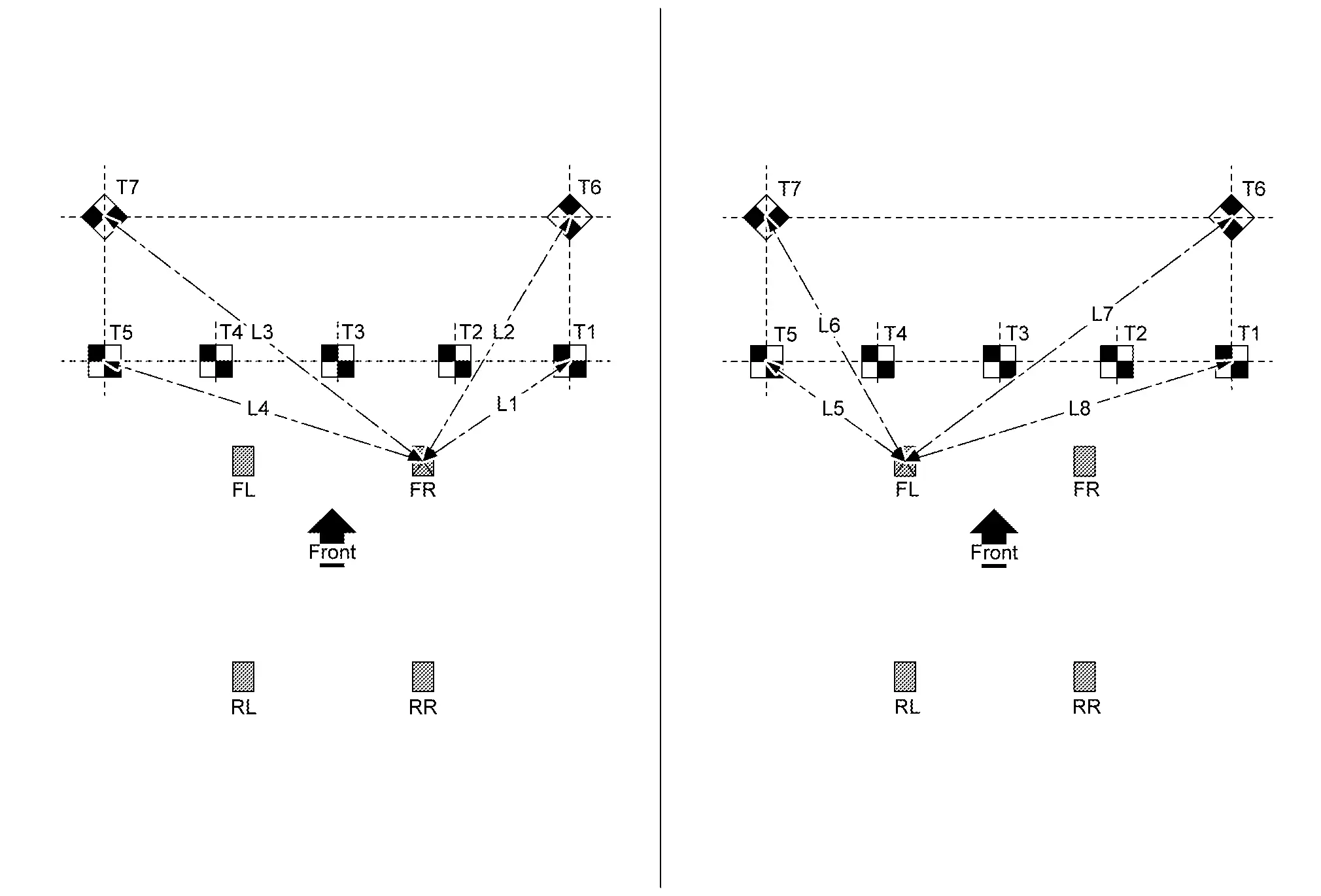
L1 Distance from right front axle center marking to target T1 L2 Distance from right front axle center marking to target T6 L3 Distance from right front axle center marking to target T7 L4 Distance from right front axle center marking to target T5 L5 Distance from left front axle center marking to target T5 L6 Distance from left front axle center marking to target T7 L7 Distance from left front axle center marking to target T6 L8 Distance from left front axle center marking to target T1 Rear camera
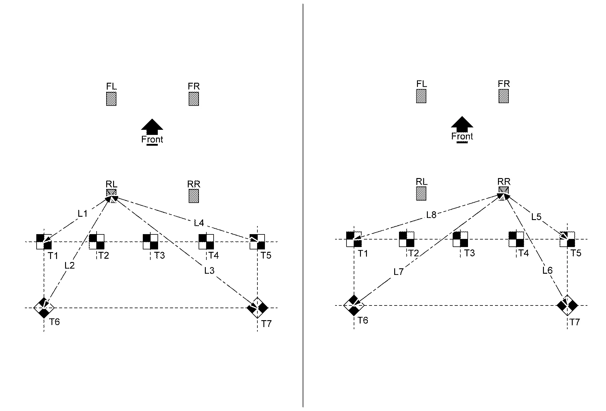
L1 Distance from left rear axle center marking to target T1 L2 Distance from left rear axle center marking to target T6 L3 Distance from left rear axle center marking to target T7 L4 Distance from left rear axle center marking to target T5 L5 Distance from right rear axle center marking to target T5 L6 Distance from right rear axle center marking to target T7 L7 Distance from right rear axle center marking to target T6 L8 Distance from right rear axle center marking to target T1
GO TO 7.
AXLE CENTER AND TARGET HEIGHT MEASUREMENT
Prepare laser leveler (KV 991 20 000).
Set laser leveler according with following camera position.
Left side camera: place radius 200 mm (7.87 in) from right front axle center position.
Right side camera: place radius 200 mm (7.87 in) from left front axle center position.
Front camera: place radius 200 mm (7.87 in) from front emblem center position.
Turn ON.
NOTE:When move laser leveler, turn OFF.
Check air bubbles and adjust the level of laser leveler.
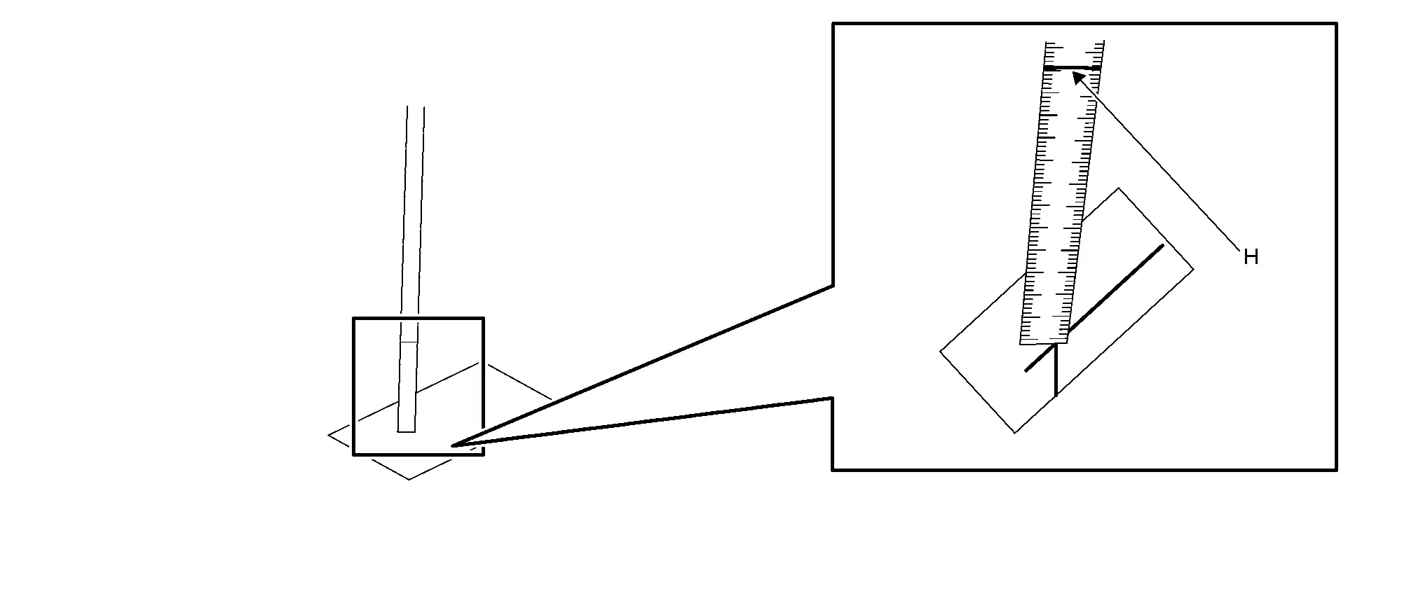
Horizontally irradiate the laser light, and stand the measure at the center position of the targets (T1) - (T7). Read the height (H) of the laser irradiated on the measure.
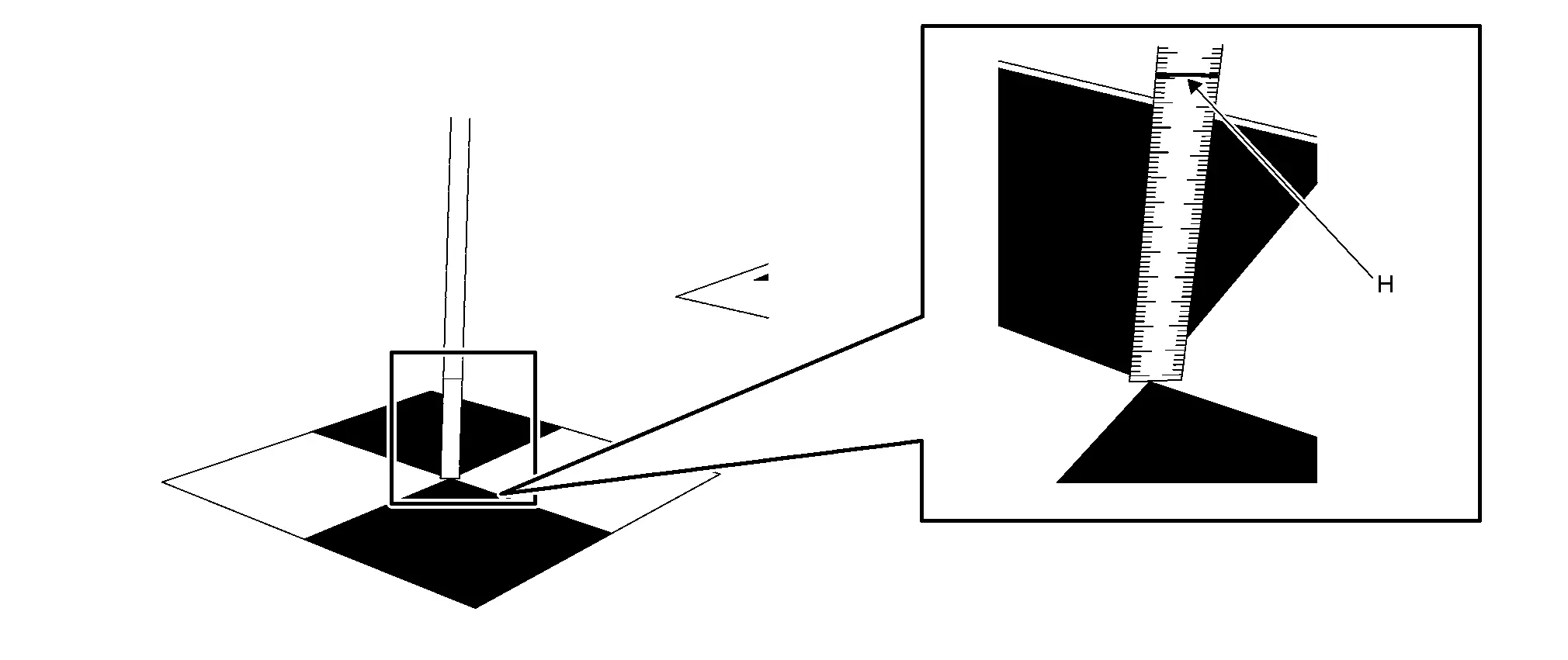
Horizontally irradiate the laser beam and set the measure at the position of 4 points on the axle center point road marked in advance. Read the height (H) of the laser irradiated on the measure.
Left side camera
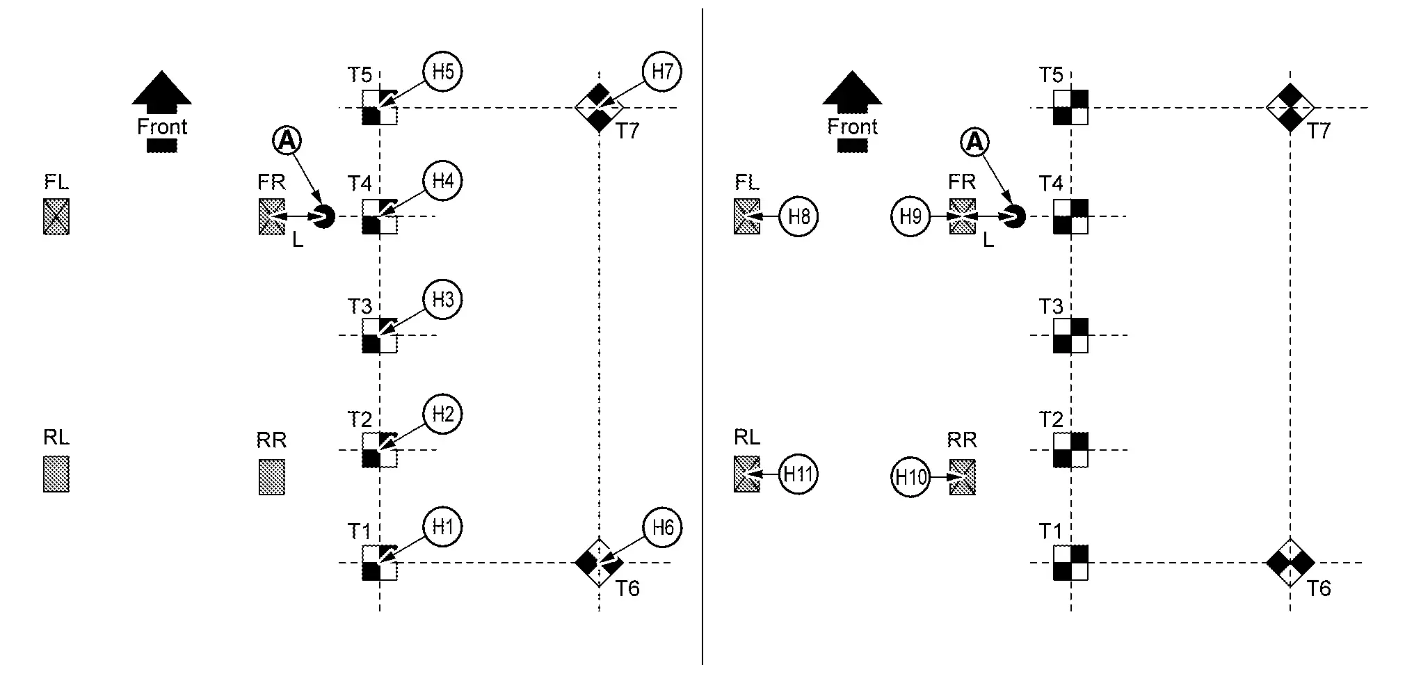
H1 Height from upper surface of target T1 H2 Height from upper surface of target T2 H3 Height from upper surface of target T3 H4 Height from upper surface of target T4 H5 Height from upper surface of target T5 H6 Height from upper surface of target T6 H7 Height from upper surface of target T7 H8 Height from left front axle center marking on the ground H9 Height from right front axle center marking on the ground H10 Height from right rear axle center marking on the ground H11 Height from left rear axle center marking on the ground : Laser leveler L : 200 mm (7.87 in) Right side camera
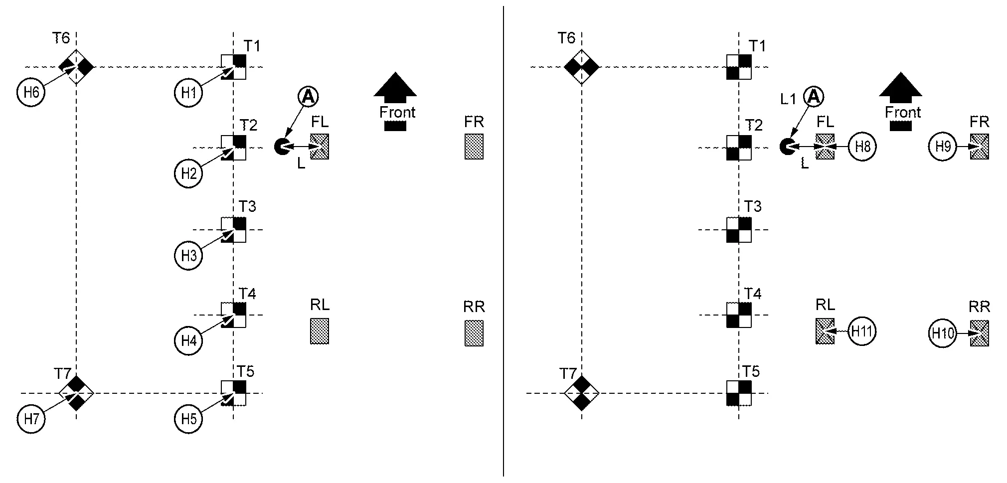
H1 Height from upper surface of target T1 H2 Height from upper surface of target T2 H3 Height from upper surface of target T3 H4 Height from upper surface of target T4 H5 Height from upper surface of target T5 H6 Height from upper surface of target T6 H7 Height from upper surface of target T7 H8 Height from left front axle center marking on the ground H9 Height from right front axle center marking on the ground H10 Height from right rear axle center marking on the ground H11 Height from left rear axle center marking on the ground : Laser leveler L : 200 mm (7.87 in) Front camera
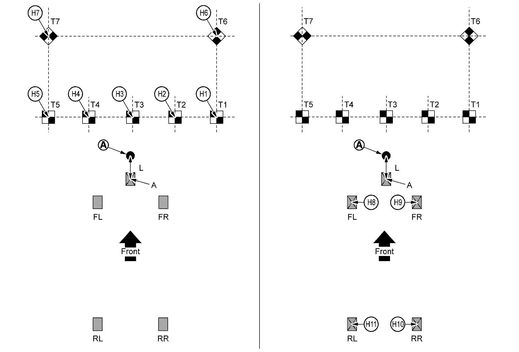
H1 Height from upper surface of target T1 H2 Height from upper surface of target T2 H3 Height from upper surface of target T3 H4 Height from upper surface of target T4 H5 Height from upper surface of target T5 H6 Height from upper surface of target T6 H7 Height from upper surface of target T7 H8 Height from left front axle center marking on the ground H9 Height from right front axle center marking on the ground H10 Height from right rear axle center marking on the ground H11 Height from left rear axle center marking on the ground Laser leveler A Center position of front emblem L 200 mm (7.87 in) Rear camera
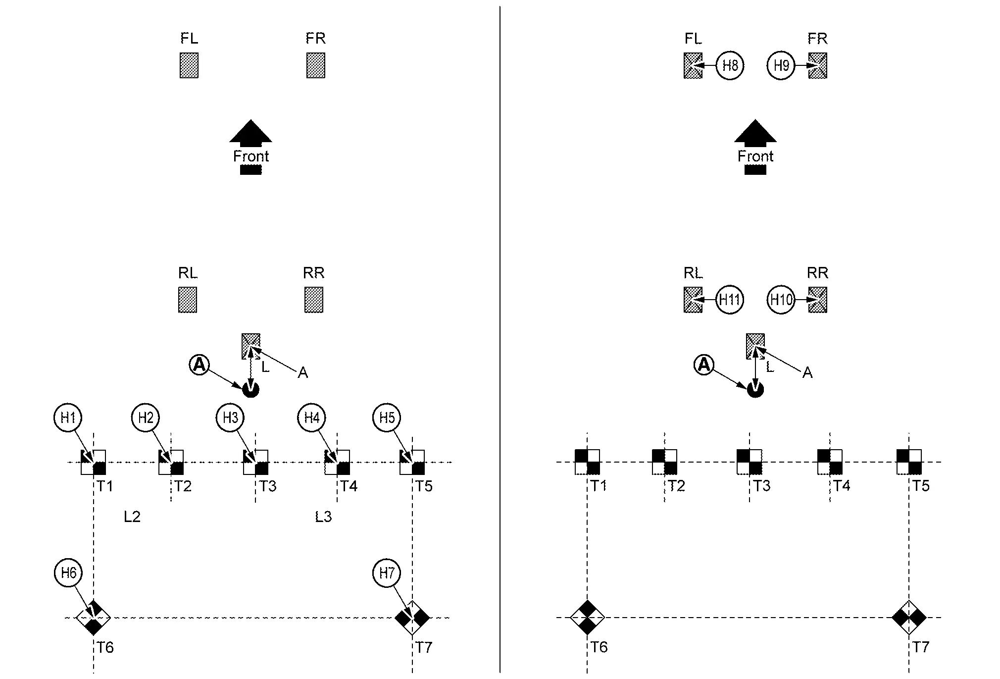
H1 Height from upper surface of target T1 H2 Height from upper surface of target T2 H3 Height from upper surface of target T3 H4 Height from upper surface of target T4 H5 Height from upper surface of target T5 H6 Height from upper surface of target T6 H7 Height from upper surface of target T7 H8 Height from left front axle center marking on the ground H9 Height from right front axle center marking on the ground H10 Height from right rear axle center marking on the ground H11 Height from left rear axle center marking on the ground Laser leveler A Center position of rear emblem L 200 mm (7.87 in)
GO TO 8.
INPUT MEASUREMENT RESULT
Input distance measurement result with mm to CONSULT.
Input height measurement result with mm to CONSULT.
Is the calibration result written correctly?
YES>>END
NO-1>>"Input value is incorrect Please input correct value" display: Check the measurement result and enter the correct value.
NO-2>>"Camera data write failed" is displayed: Restart camera calibration from the beginning. If writing fails even after re-execution, replace the corresponding camera.
TARGET MARK SAMPLE
NOTE:
Change the magnification of print to 200 mm (7.87 in) �~ 200 mm (7.87 in) and print the target mark sample.
 3d View Rotation
...

Other materials:
General Specification
Applied model Engine VR35DDTT Axle 2WD 4WD Transmission model GE9R01A Transmission gear ratio 1st 5.425 2nd 3.263 3rd 2.250 4th 1.649 5th 1.221 6th 1.000 7th 0.862 8th 0.713 9th 0.597 Reverse 4.799 A/T fluid Recommended fluid Fluids and Lubricants Capacity ...
Booster seats
Precautions on booster seats
WARNING
Improper use of a booster seat and seat belt in the Nissan Armada significantly
increases the risk of serious injury or fatal consequences for a child in the event
of a sudden stop or collision.
Ensure that the shoulder belt in the Nissan Armada is corr ...
Types of tires
Basic information
WARNING
When replacing tires on your Nissan Armada, always ensure that all four
tires are identical in type (for example: Summer, All Season, or Snow) as well
as in construction.
Using mismatched tires can negatively impact vehicle stability, handling,
and safety ...

0.0056