Exploded View
 |
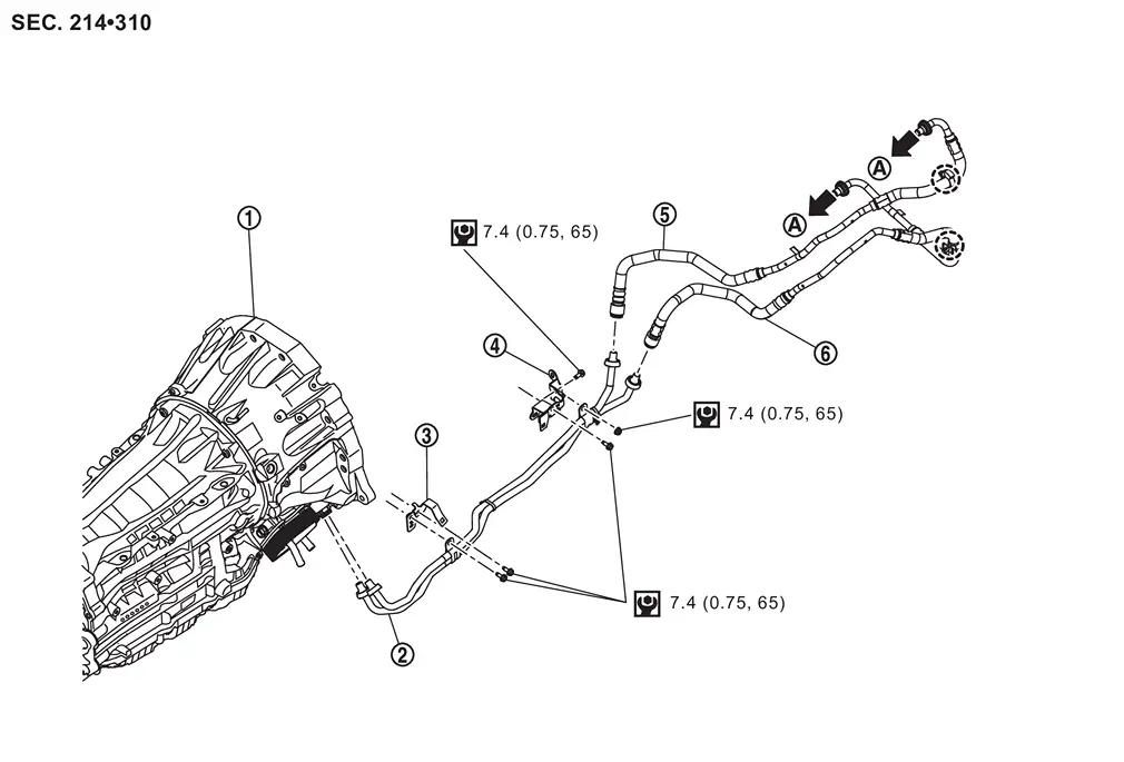
A/T assembly |  |
A/T fluid cooler tube assembly |  |
Bracket |
 |
Bracket |  |
A/T fluid cooler hose A |  |
A/T fluid cooler hose B |
 |
To A/T fluid cooler. Refer to Exploded View. | ||||
 |
: Clip | ||||
 |
: N·m (kg-m, in-lb) | ||||
Removal and Installation
WARNING:
-
Jacking up or lift up the vehicle may the vehicle height to go down which cause a personal injury and/or damage to the air suspension component parts. Refer to Precaution for when Jacking and Lifting Up the vehicle with Electronic Air Suspension System.
REMOVAL
 NOTE:
NOTE:
When removing components such as hoses, tubes/lines, etc., cap or plug openings to prevent fluid from spilling.
CAUTION:
Perform this step when the engine is cold.
Remove front bumper. Refer to Exploded View.
Remove front under cover. Refer to Removal and Installation.
Drain A/T fluid. Refer to Draining.
Remove A/T fluid cooler hose A and B from A/T fluid cooler. Refer to Removal and Installation.
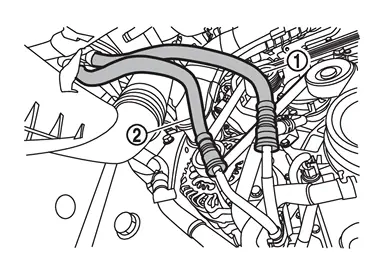
Remove A/T fluid cooler hose A and A/T fluid cooler hose B from A/T fluid cooler tube assembly using the following procedure:
-
Remove A/T fluid cooler tube cap
from A/T fluid cooler tube assembly .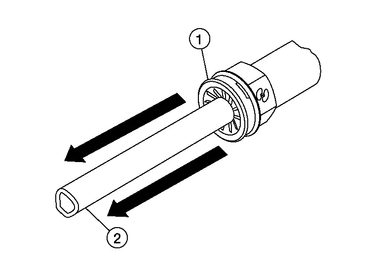
-
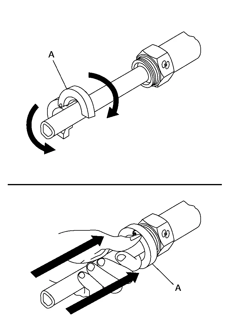
Install suitable disconnect tool (A) (commercial service tool) on to the A/T fluid cooler tube assembly at the A/T fluid cooler hose side.
-
Rotate suitable disconnect tool (A) (commercial service tool) counter clockwise 60 degrees to release snap ring.
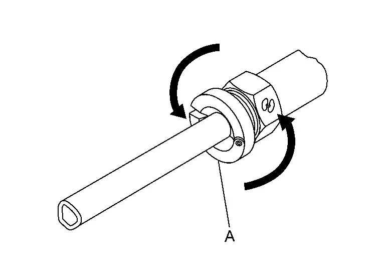
-
Remove A/T fluid cooler tube
from A/T fluid cooler hose.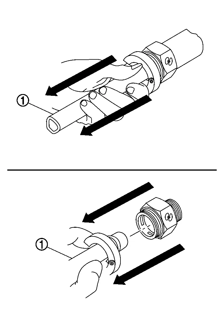
Remove the water hose clip A and B from the A/T fluid cooler tube assembly bracket. Refer to Removal and Installation.
Remove A/T fluid cooler tube assembly mounting nut ( ) and remove A/T fluid cooler tube assembly from bracket.
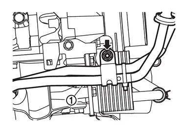
Remove A/T fluid cooler tube assembly mounting bolt () and remove A/T fluid cooler tube assembly from bracket.
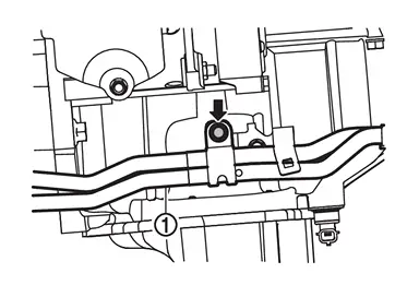
Remove A/T fluid cooler tube assembly  from A/T assembly using the following procedure:
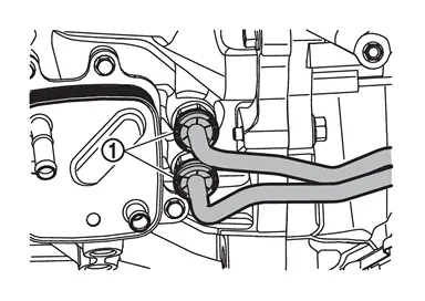
-
Remove A/T fluid cooler tube cap
from A/T fluid cooler tube assembly  .
. -
Install suitable disconnect tool (A) (commercial service tool) on to the A/T fluid cooler tube assembly at the A/T assembly side.
-
Rotate suitable disconnect tool (A) (commercial service tool) counter clockwise 60 degrees to release snap ring.
-
Remove A/T fluid cooler tube
from A/T assembly.
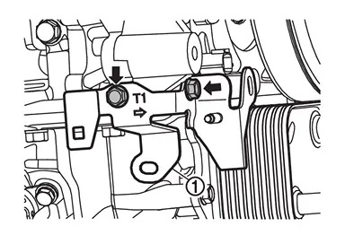
Remove bracket mounting bolts () and remove bracket .
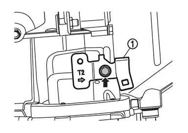
Remove bracket mounting bolt () and remove bracket .
INSTALLATION
-
Installation is in the reverse order of removal.
-
Fill A/T fluid after installation. Refer to Refilling.
Inspection and Adjustment
INSPECTION AFTER INSTALLATION
Check for A/T fluid leakage. Refer to Inspecton.
ADJUSTMENT AFTER INSTALLATION
Adjust A/T fluid level. Refer to Adjustment.
Other materials
Intelligent Around View Monitor system operation
The Nissan Armada Intelligent Around View Monitor utilizes multiple strategically
positioned cameras 1, including units mounted in the front grille, beneath the outside
mirrors, and above the rear license plate, to create a comprehensive multi-angle
view of the vehicle surroundings.
Basic ...
I-BSI system limitations
WARNING
The following limitations apply to the Nissan Armada Intelligent Blind Spot
Intervention (I-BSI) system. Failure to operate the vehicle within these limitations
may result in serious injury or death.
The Nissan Armada I-BSI system cannot detect all vehicles or objects
in every si ...
Intelligent Rear View Mirror
Exploded View
Intelligent rear view mirror cover LH
Intelligent rear view mirror cover RH
Intelligent rear view mirror
Inside mirror base
: Pawl
: N·m (kg-m, in-lb)
Removal and Installation
CAUTION:
Never move intelligent rear view mirror beyond t ...