Work Procedure
INSPECTION START
-
Check service records for any recent repairs that may indicate a related malfunction, or a current need for scheduled maintenance.
-
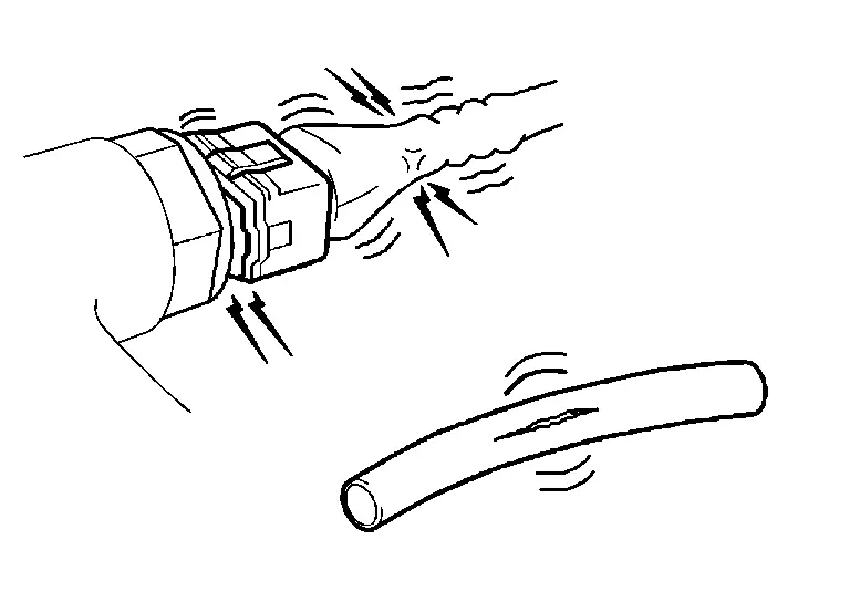
Open engine hood and check the following:
-
Harness connectors for improper connections
-
Wiring harness for improper connections, pinches and cut
-
Vacuum hoses for splits, kinks and improper connections
-
Hoses and ducts for leaks
-
Air cleaner clogging
-
Gasket
-
-
Confirm that electrical or mechanical loads are not applied.
-
Headlamp switch is OFF.
-
Air conditioner switch is OFF.
-
Rear window defogger switch is OFF.
-
Steering wheel is in the straight-ahead position, etc.
-
-
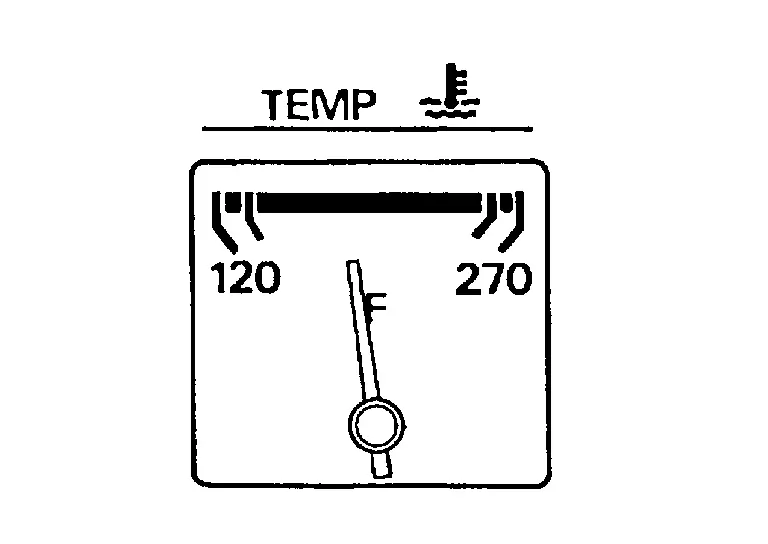
Start engine and warm it up until engine coolant temperature indicator points the middle of gauge.
Ensure engine stays below 1,000 rpm.
-
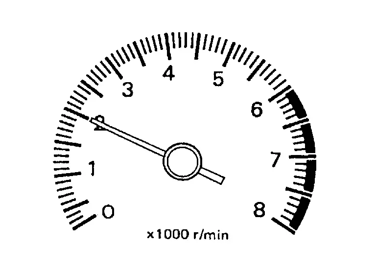
Run engine at about 2,000 rpm for about 2 minutes under no load.
-
Make sure that no DTC is displayed with CONSULT or GST.
Are any DTCs detected?
YES>>GO TO 2.
NO>>GO TO 3.
REPAIR OR REPLACE
Repair or replace components as necessary according to corresponding Diagnosis Procedure.
>>
GO TO 3
CHECK IDLE SPEED
-
Run engine at about 2,000 rpm for about 2 minutes under no load.
-
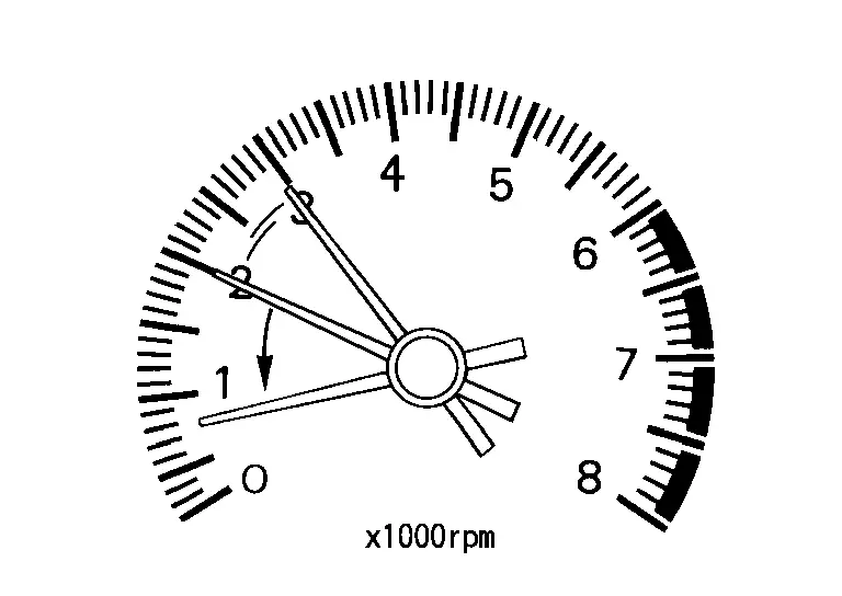
Rev engine (2,000 to 2,900 rpm) two or three times under no load, then run engine at idle speed for about 1 minute.
-
Check idle speed.
For procedure, refer to Inspection.
For specification, refer to Idle Speed.
Is the inspection result normal?
YES>>GO TO 10.
NO>>GO TO 4.
PERFORM ACCELERATOR PEDAL RELEASED POSITION LEARNING
-
Stop engine.
-
Perform Accelerator Pedal Released Position Learning. Refer to Work Procedure.
>>
GO TO 5.
PERFORM THROTTLE VALVE CLOSED POSITION LEARNING
Perform Throttle Valve Closed Position Learning. Refer to Work Procedure.
>>
GO TO 6.
PERFORM IDLE AIR VOLUME LEARNING
Perform Idle Air Volume Learning. Refer to Work Procedure.
Is Idle Air Volume Learning carried out successfully?
YES>>GO TO 7.
NO>>Follow the instruction of Idle Air Volume Learning. Then GO TO 4.
CHECK IDLE SPEED AGAIN
-
Start engine and warm it up to normal operating temperature.
-
Check idle speed.
For procedure, refer to Inspection.
For specification, refer to Idle Speed.
Is the inspection result normal?
YES>>GO TO 10.
NO>>GO TO 8.
DETECT MALFUNCTIONING PART
Check the Following.
-
Check camshaft position sensor (PHASE) and circuit. Refer to Component Inspection.
-
Check crankshaft position sensor (POS) and circuit. Refer to Component Inspection.
Is the inspection result normal?
YES>>GO TO 9.
NO>>Repair or replace. Then GO TO 4.
CHECK ECM FUNCTION
-
Substitute with a non-malfunctioning ECM to check ECM function. (ECM may be the cause of the incident, although this is rare.)
-
Perform initialization of IVIS (NATS) system and registration of all IVIS (NATS) ignition key IDs. Refer to Work Procedure.
>>
GO TO 4.
CHECK IGNITION TIMING
-
Run engine at idle.
-
Check ignition timing.
For procedure, refer to IGNITION TIMING : Periodic Maintenance.
For specification, refer to Ignition Timing.
Is the inspection result normal?
YES>>GO TO 19.
NO>>GO TO 11.
PERFORM ACCELERATOR PEDAL RELEASED POSITION LEARNING
-
Stop engine.
-
Perform Accelerator Pedal Released Position Learning. Refer to Work Procedure.
>>
GO TO 12.
PERFORM THROTTLE VALVE CLOSED POSITION LEARNING
Perform Throttle Valve Closed Position Learning. Refer to Work Procedure.
>>
GO TO 13.
PERFORM IDLE AIR VOLUME LEARNING
Perform Idle Air Volume Learning. Refer to Work Procedure.
Is Idle Air Volume Learning carried out successfully?
YES>>GO TO 14.
NO>>Follow the instruction of Idle Air Volume Learning. Then GO TO 4.
CHECK IDLE SPEED AGAIN
-
Start engine and warm it up to normal operating temperature.
-
Check idle speed.
For procedure, refer to Inspection.
For specification, refer to Idle Speed.
Is the inspection result normal?
YES>>GO TO 15.
NO>>GO TO 17.
CHECK IGNITION TIMING AGAIN
-
Run engine at idle.
-
Check ignition timing.
For procedure, refer toIGNITION TIMING : Periodic Maintenance.
For specification, refer to Ignition Timing.
Is the inspection result normal?
YES>>GO TO 19.
NO>>GO TO 16.
CHECK TIMING CHAIN INSTALLATION
Check timing chain installation. Refer to Exploded View.
Is the inspection result normal?
YES>>GO TO 17.
NO>>Repair the timing chain installation. Then GO TO 4.
DETECT MALFUNCTIONING PART
Check the following.
-
Check camshaft position sensor (PHASE) and circuit. Refer to Component Inspection.
-
Check crankshaft position sensor (POS) and circuit. Refer to Component Inspection.
Is the inspection result normal?
YES>>GO TO 18.
NO>>Repair or replace. Then GO TO 4.
CHECK ECM FUNCTION
-
Substitute with a non-malfunctioning ECM to check ECM function. (ECM may be the cause of the incident, although this is rare.)
-
Perform initialization of IVIS (NATS) system and registration of all IVIS (NATS) ignition key IDs. Refer to Work Procedure.
>>
GO TO 4.
INSPECTION END
If ECM is replaced during this BASIC INSPECTION procedure, Refer to Work Procedure.
>>
INSPECTION END
Other materials
Door Motor
Exploded View
FRONT
Front heater & cooling unit assembly
Front air mix door motor (driver side)
Front mode door motor
Front blower unit assembly
Intake door motor
Front air mix door motor (passenger side)
: vehicle front
REAR
Rear A/C unit assembly
Rear mode door motor ...
Advanced Ambient Light (rear Door Upper)
Exploded View
Advanced ambient light (rear door upper) is integrated structure with rear door finisher. For exploded view of rear door finisher, refer to Exploded View.
Replacement
CAUTION:
Disconnect the battery negative terminal or remove power circuit fuse when performing the operation for prev ...
Driving Video Recorder Control Module
Removal and Installation
REMOVALCAUTION:
Before replacing driving video recorder control module, perform “ADDITIONAL SERVICE WHEN REPLACING DRIVING VIDEO RECORDER CONTROL MODULE”. For details, refer to Work Procedure.
Before replacing the driving video recorder control module, the customer s ...