Work Flow
OVERALL SEQUENCE
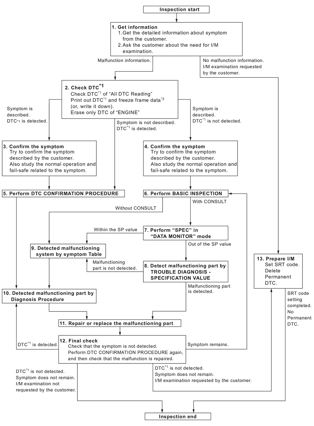
| *1: Include 1st trip DTC. | |||||
| *2: Include 1st trip freeze frame data. |
DETAILED FLOW
GET INFORMATION FOR SYMPTOM
-
Get the detailed information from the customer about the symptom (the condition and the environment when the incident/malfunction occurred) using the “Diagnostic Work Sheet”. (Refer to Diagnostic Work Sheet.)
-
Ask if the customer requests I/M examination.
Malfunction information, obtained>>
GO TO 2.
No Malfunction information, but a request for I/M examination>>GO TO 13.
CHECK DTC
With CONSULT
-
Check DTC of “All DTC Reading”.
-
Perform the following procedure if DTC is displayed.
-
Record DTC and freeze frame data. (Print them out with CONSULT or GST.)
-
Erase only DTC of “ECM”. Refer to “How to Erase DTC and 1st Trip DTC” in Refer to CONSULT Function.
-
Ignition switch OFF.
-
Study the relationship between the cause detected by DTC and the symptom described by the customer. (Symptom Table is useful. Refer to Symptom Table.)
-
Are any symptoms described and any DTCs detected?
Symptom is described, DTC is detected>>GO TO 3.
Symptom is described, DTC is not detected>>GO TO 4.
Symptom is not described, DTC is detected>>GO TO 5.
CONFIRM THE SYMPTOM
Try to confirm the symptom described by the customer (except MIL ON).
Also study the normal operation and fail-safe related to the symptom. Refer to Description. and Refer to Fail-safe.
Diagnosis Work Sheet is useful to verify the incident.
Verify relation between the symptom and the condition when the symptom is detected.
>>
GO TO 5.
CONFIRM THE SYMPTOM
Try to confirm the symptom described by the customer.
Also study the normal operation and fail-safe related to the symptom. Refer to Description. and Refer to Fail-safe.
Diagnosis Work Sheet is useful to verify the incident.
Verify relation between the symptom and the condition when the symptom is detected.
>>
GO TO 6.
PERFORM DTC CONFIRMATION PROCEDURE
Perform DTC CONFIRMATION PROCEDURE for the displayed DTC, and then make sure that DTC is detected again.
If two or more DTCs are detected, Refer to DTC Inspection Priority Chart.
 NOTE:
NOTE:
-
Freeze frame data is useful if the DTC is not detected.
-
Perform Component Function Check if DTC CONFIRMATION PROCEDURE is not included on Service Manual. This simplified check procedure is an effective alternative though DTC cannot be detected during this check.
If the result of Component Function Check is NG, it is the same as the detection of DTC by DTC CONFIRMATION PROCEDURE.
Is DTC detected?
YES>>GO TO 10.
NO>>Check according to Refer to Intermittent Incident.
PERFORM BASIC INSPECTION
Perform Refer to Work Procedure.
Do you have CONSULT?
YES>>GO TO 7.
NO>>GO TO 9.
CHECK REFERENCE OF DATA MONITOR MODE
With CONSULT
-
On CONSULT screen, select “ECM”>>“Data monitor”.
-
Check that “Mass air flow sensor bank 1”, “B/FUEL SCHDL”, and "Air fuel ratio ALPHA (bank 1)" are within the SP value. Refer to Component Function Check.
Is the measurement value within the SP value?
YES>>GO TO 9.
NO>>GO TO 8.
DETECT MALFUNCTIONING PART BY TROUBLE DIAGNOSIS - SPECIFICATION VALUE
Detect malfunctioning part according to Refer to Diagnosis Procedure.
Is a malfunctioning part detected?
YES>>GO TO 11.
NO>>GO TO 9.
DETECT MALFUNCTIONING SYSTEM BY SYMPTOM TABLE
Detect malfunctioning system according to Refer to Symptom Table. based on the confirmed symptom in step 4, and determine the trouble diagnosis order based on possible causes and symptoms.
>>
GO TO 10.
DETECT MALFUNCTIONING PART BY DIAGNOSIS PROCEDURE
Inspect according to Diagnosis Procedure of the system.
NOTE:
The Diagnosis Procedure in EC section described based on open circuit inspection. A short circuit inspection is also required for the circuit check in the Diagnosis Procedure. For details, Refer to Circuit Inspection.
Is a malfunctioning part detected?
YES>>GO TO 11.
NO>>Monitor input data from related sensors or check voltage of related ECM terminals using CONSULT. Refer to Physical Values.
REPAIR OR REPLACE THE MALFUNCTIONING PART
With CONSULT
-
Repair or replace the malfunctioning part.
-
Reconnect parts or connectors disconnected during Diagnosis Procedure again after repair and replacement.
-
Check DTC. If DTC is displayed, erase it. Refer to “How to Erase DTC and 1st Trip DTC” in Refer to CONSULT Function.
>>
GO TO 12.
FINAL CHECK
With CONSULT
When DTC was detected in step 2, perform DTC CONFIRMATION PROCEDURE or Component Function Check again, and then make sure that the malfunction have been completely repaired.
When symptom was described from the customer, refer to confirmed symptom in step 3 or 4, and make sure that the symptom is not detected.
Is DTC detected and does symptom remain?
YES-1>>DTC is detected: GO TO 10.
YES-2>>Symptom remains: GO TO 6.
NO-1>>No request for I/M examination from the customer: Before returning the vehicle to the customer, always erase unnecessary DTC in ECM and TCM. Refer to “How to Erase DTC and 1st Trip DTC” in Refer to CONSULT Function.
NO-2>>I/M examination, requested from the customer: GO TO 13.
PREPARE FOR I/M EXAMINATION
-
Set SRT codes. Refer to Work Procedure.
-
Erase permanent DTCs. Refer to Work Procedure (Group A), Work Procedure (Group B).
>>
INSPECTION END.
Diagnostic Work Sheet
DESCRIPTION
There are many operating conditions that lead to the malfunction of engine components. A good grasp of such conditions can make troubleshooting faster and more accurate.
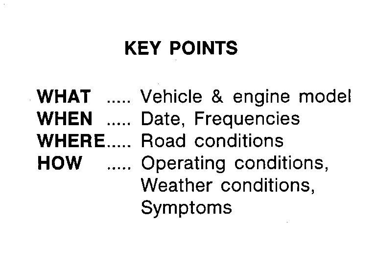
In general, each customer feels differently about an incident. It is important to fully understand the symptoms or conditions for a customer complaint.
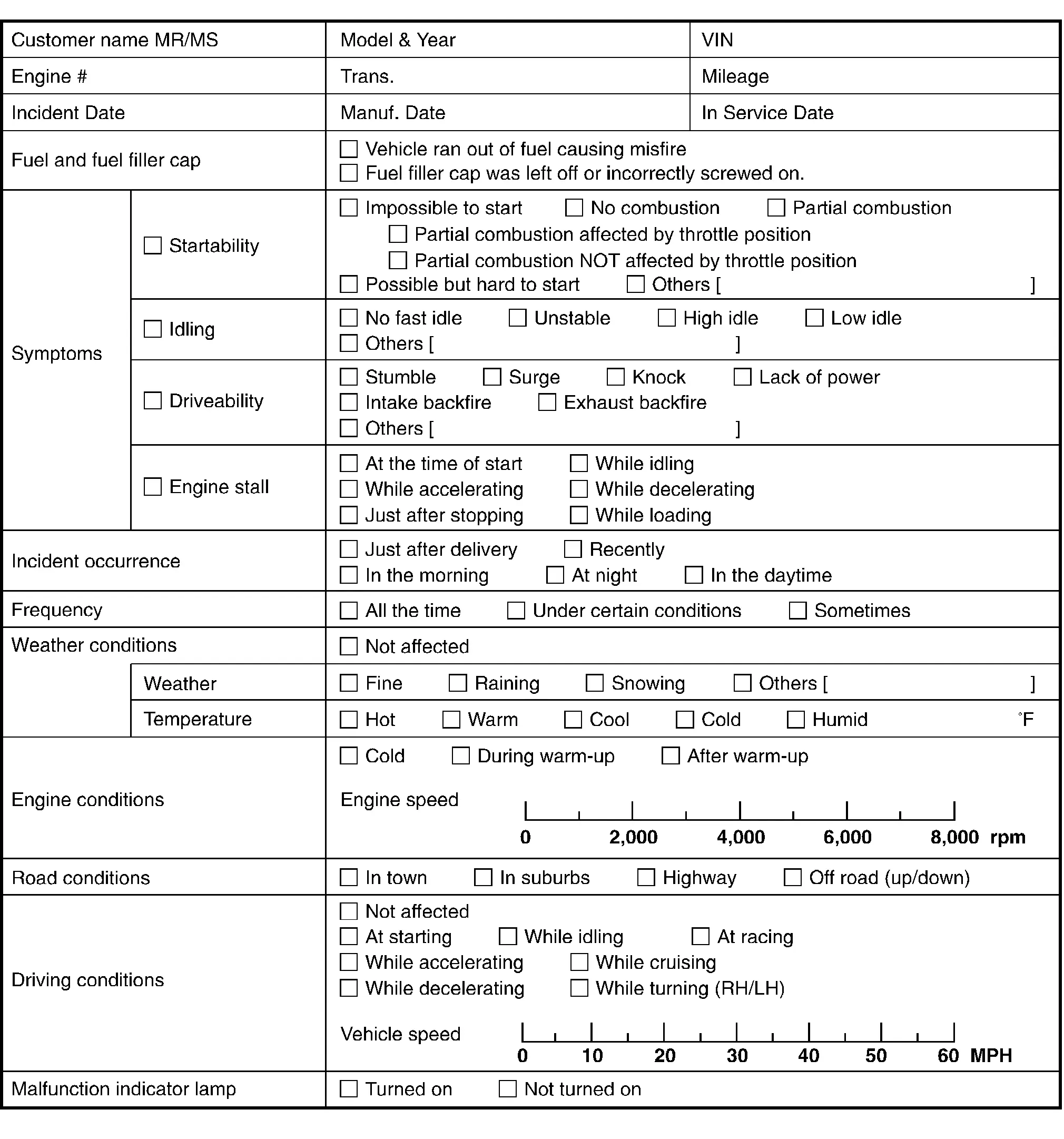
Utilize a diagnostic worksheet like the WORKSHEET SAMPLE below in order to organize all the information for troubleshooting.
Some conditions may cause the MIL to illuminate steady or blink and DTC to be detected. Examples:
-
Vehicle ran out of fuel, which caused the engine to misfire.
WORKSHEET SAMPLE
Other materials
Ventilated seats
Basic information
CAUTION
In the Nissan Armada, avoid using the ventilated seat system for long
periods when the seat is unoccupied to prevent unnecessary wear and energy consumption.
Do not place heavy, sharp, or pointed objects on the Nissan Armada seats,
as this may damage the intern ...
Brake Caliper Assembly
Exploded View
REMOVAL
Brake caliper assembly
: N·m (kg-m, ft-lb)
DISASSEMBLY
Cap
Bleeder valve
Cylinder body
Sliding pin
Bushing
Sliding pin boot
Piston seal
Piston
Piston boot
Torque member
: vehicle ...
Calibration of Automatic Back Door Position Information
Description
When the following work is performed, it is necessary to perform initial setting of automatic back door position information to operate automatic back door system. Refer to Work Procedure.
After removing and installing, or replacing back door assembly
After removing and installing, or ...