Exploded View
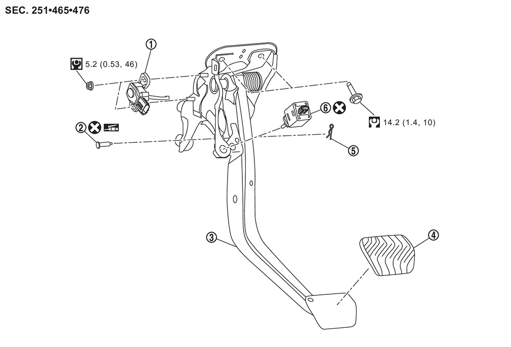
 |
Stroke sensor |  |
Clevis pin |  |
Brake pedal assembly |
 |
Brake pedal pad |  |
Snap pin |  |
Stop lamp switch |
 |
: N·m (kg-m, ft-lb) | ||||
 |
: N·m (kg-m, in-lb) | ||||
 |
: Apply Nissan multi-purpose Special Grease No.2 or equivalent. | ||||
 |
: Always replace after every disassembly. | ||||
Removal and Installation
REMOVAL
Remove driver knee air bag module. Refer to Removal and Installation.
Remove BCM. Refer to Removal and Installation.
Remove fuse block (J/B).
Disconnect the stop lamp switch harness connectors.
Remove stop lamp switch , follow the procedure below.
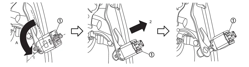
| A | : About 90 degree |
Disconnect the stroke sensor harness connector.
Remove stroke sensor if necessary.
Remove snap pin and clevis pin from clevis of electrical brake control unit .
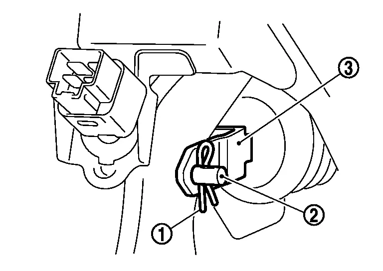
Remove harness clip from brake pedal.
Remove the electrical brake control unit mounting nuts from brake pedal assembly. Refer to Removal & Installation.
Remove the brake pedal assembly mounting bolts, and remove brake pedal assembly.
CAUTION:
Hold the electrical brake control unit so as not to drop out or contact them other parts.
Perform inspection after removal. Refer to Inspection.
INSTALLATION
Note the following, and install in the reverse order of removal.
-
Never reuse stop lamp switch.
-
Never reuse the clevis pin.
-
Apply the Nissan multi-purpose Special Grease No.2 or equivalent to the clevis pin and the mating faces.
 NOTE:
NOTE:
The clevis pin may be inserted in either direction.
-
Never impact brake pedal such as drop and interference with tools and parts.
-
Replace brake pedal when impacting brake pedal.
-
Install stop lamp switch
, follow the procedure below.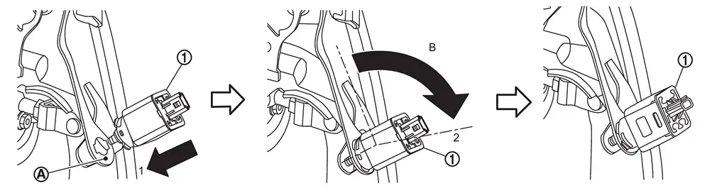
-
Penetrate the clip hole of stop lamp switch mounting bracket and firmly push the direction (1) the stop lamp switch against the stop lamp switch mounting bracket
 .
.B : About 90 degree -
Turn the stop lamp switch clockwise (2) until it stops.
-
-
Perform adjustment after installation. Refer to Adjustment.
-
Perform stroke sensor calibration when brake pedal assembly removed and installed, or replaced. Refer to Work Procedure.
-
Perform stroke sensor calibration when stroke sensor removed and installed, or replaced. Refer to Work Procedure.
Inspection
INSPECTION AFTER REMOVAL
Check the brake pedal assembly for bend, damage, and cracks on the welded parts. If any is found, replace brake pedal assembly.
Adjustment
ADJUSTMENT AFTER INSTALLATION
-
Adjust each item of brake pedal after installing the brake pedal assembly to the vehicle. Refer to Inspection and Adjustment.
-
Perform stroke sensor 0 point learning. Refer to Work Procedure.
Other materials
How to use remote keyless entry function
WARNING
In the Nissan Armada, radio frequency signals generated by the Intelligent
Key may interfere with certain medical devices.
Individuals using pacemakers or other electronic medical equipment should
consult the device manufacturer before using the Nissan Armada Intelligent Key.
...
Low Tire Pressure Location Indicator Does Not Display
Description
When low tire pressure, low tire location indicator does not display though low tire pressure warning lamp turns ON.
Diagnosis Procedure
CHECK COMBINATION METER
Check combination meter. Refer to Work flow.
Is the inspection result normal?
YES>>
GO TO 2.
NO>>
Repair or repla ...
Precautions
Precautions for Removing Battery Terminal
When disconnecting the 12V battery terminal, turn off the ACC power before disconnecting the 12V battery terminal, observing “How to disconnect 12V battery terminal� described below.
NOTE:
Some ECUs operate for a certain fixed time even after ignit ...