Exploded View
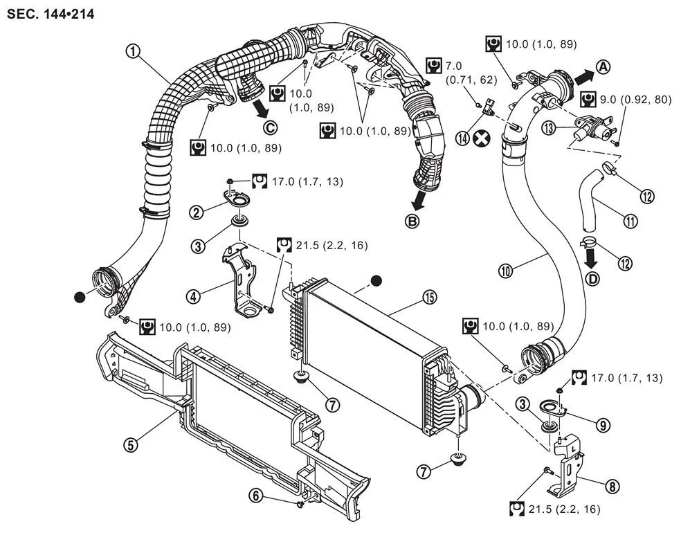
 |
Air inlet tube 1 |  |
Bracket 1 |  |
Mounting rubber (upper) |
 |
Bracket 2 |  |
Charge air cooler cover |  |
Clip |
 |
Mounting rubber (lower) |  |
Bracket 3 |  |
Bracket 4 |
 |
Air inlet tube 2 |  |
Air inlet hose |  |
Clamp |
 |
Recirculation valve |  |
Turbocharger boost sensor |  |
Charge air cooler |
 |
To electric throttle control actuator. Refer to Exploded View. |  |
To turbocharger assembly (bank 2). Refer to Exploded View. |  |
To turbocharger assembly (bank 1). Refer to Exploded View. |
 |
To air duct. Refer to Exploded View. | ||||
 |
: Always replace after every disassembly. | ||||
 |
: N·m (kg-m, in-lb) | ||||
 |
: N·m (kg-m, ft-lb) | ||||
 |
: Indicates that the parts is connected at points with same symbols in actual vehicle. | ||||
Removal & Installation
WARNING:
-
Jacking up or lift up the vehicle may the vehicle height to go down which cause a personal injury and/or damage to the air suspension component parts. Refer to Precaution for when Jacking and Lifting Up the vehicle with Electronic Air Suspension System.
REMOVAL
Remove engine cover. Refer to Removal and Installation.
Remove front under cover using a power tool (commercial service tool). Refer to Removal and Installation.
Remove air inlet tube 1 and air inlet tube 2 of charge air cooler side as follows.Remove mounting bolt of air inlet tube 1 .
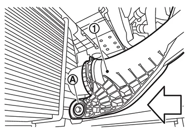
| : vehicle front |
of air inlet tube 1 in the direction of the arrow ( ) to release the lock.
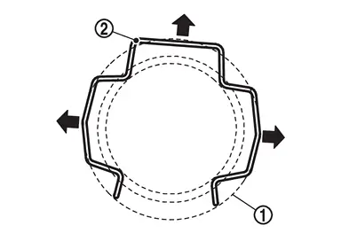
of air inlet tube 2 .
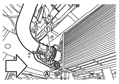
| : vehicle front |
of air inlet tube 2 in the direction of the arrow () to release the lock.
Remove air inlet tube 2 on the electric throttle control actuator side as follows.Disconnect turbocharger boost sensor harness connector .
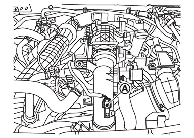
.
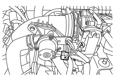
from recirculation valve .
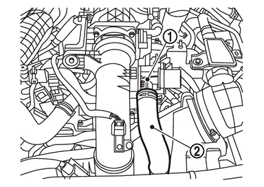
of air inlet tube 2 .
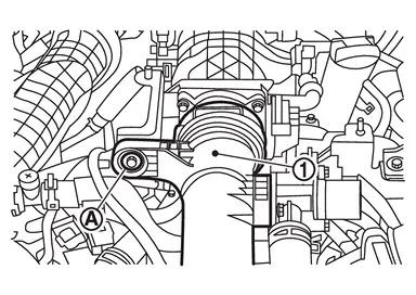
of air inlet tube 1 in the direction of the view arrow () to release the lock.
Remove air inlet tube 1 of turbocharger (bank 1 side) and turbocharger (bank 2 side) as follows.Remove mounting bolt from air inlet tube 1 .
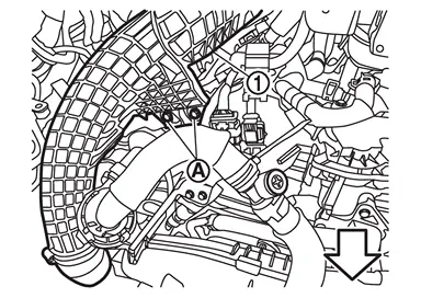
| : Engine front |
from air inlet tube 1 .
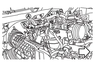
| : Engine front |
from air inlet tube 1 .
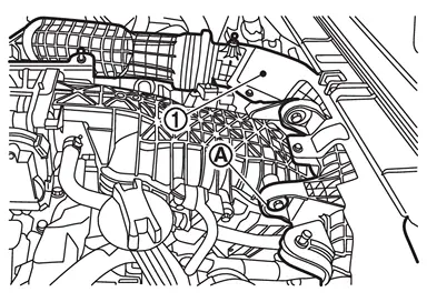
of air inlet tube 1 in the direction of the view arrow () to release the lock.
from turbocharger (bank 1 side) .
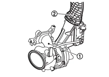
of air inlet tube 1 in the direction of the view arrow () to release the lock.
from turbocharger (bank 2 side) .
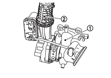
Remove charge air cooler as follows.
 NOTE:
NOTE:
If only remove the charge air cooler, there is no need to remove the air inlet tube (1 and 2). Charge air cooler can be remove by disconnect the connection between the air inlet tubes (1 and 2) and the charge air cooler.
Remove front grille.-
OFF ROAD MODELS: Refer to Removal and Installation.
-
CITY MODELS: Refer to Removal and Installation.
-
OFF ROAD MODELS: Refer to Removal and Installation.
-
CITY MODELS: Refer to Removal and Installation.
and remove bracket 1 and bracket 4 .
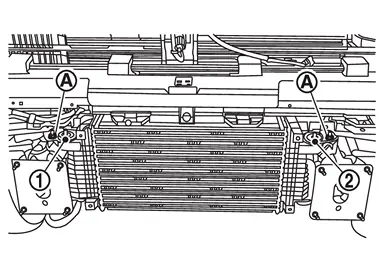
.
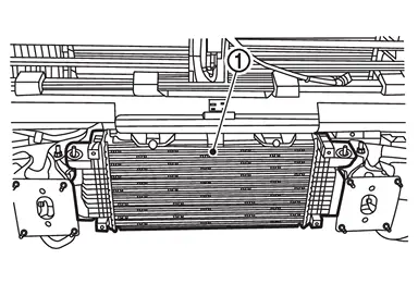
INSTALLATION
Note the following, and install in the reverse order of removal.
-
Air inlet tube 1 and air inlet tube 2 connections lock with an audible “click” when plugged in.
Inspection
INSPECTION AFTER REMOVAL
Check air passages of charge air cooler core and fins for clogging, leaks or defo rmation.
Clean or replace charge air cooler if necessary.
-
Be careful not to deform core fins.
Other materials
Front Door Lock Assembly
Removal and Installation
REMOVALRemove front door finisher. Refer to Removal and Installation.
Remove front door module assembly. Refer to Removal and Installation.
Remove front door outside handle bracket. Refer to Removal and Installation.
Remove front door lock assembly mounting TORX bolts.
Disen ...
Rear Door Outside Handle
Removal and Installation
REMOVALRemove rear door finisher. Refer to Removal and Installation.
Remove rear door inner frame. Refer to Removal and Installation.
Disconnect rear door outside handle harness connector , and then disengage rear door outside handle harness connector fixing clip (if equipp ...
Glass Lid Guide
Exploded View
Refer to Exploded View.
Removal and Installation
REMOVALRemove drain assembly. Refer to Removal and Installation.
Remove sunshade. Refer to Removal and Installation.
Remove side trim and glass lid guide from moonroof frame assembly.
Remove side trim from glass lid guide.INSTALLATIO ...