
Nissan Armada 2025-2026 Service and Repair Manual: Disassembly and Assembly
DISASSEMBLY
Remove mounting insulators with drift [SST: ST33200000 (NI-26082)] if necessary.
Remove side shaft assembly. Refer to Disassembly and Assembly.
Remove side oil seal from gear carrier with a oil seal remover (commercial service tool).
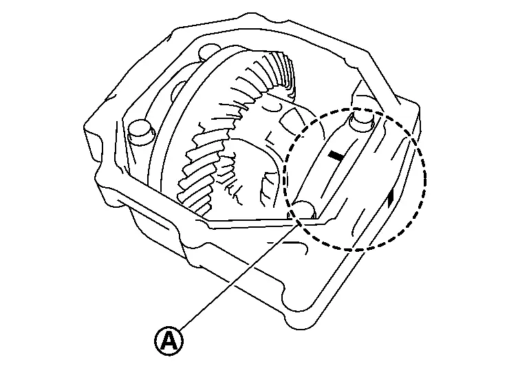
For proper reinstallation, paint matching marks  on one side of bearing cap.
CAUTION:
For matching marks, use paint. Never damage bearing caps and carrier case.
Bearing caps are manufactured as integral molding. Use the matching marks to them in their original positions.
Remove bearing caps.
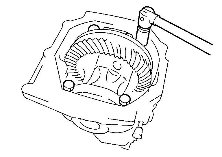
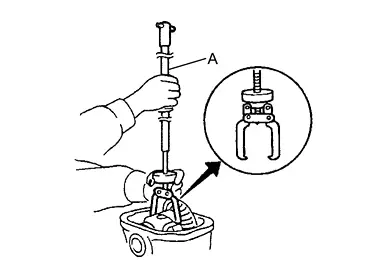
Lift the differential assembly out of the gear carrier with sliding hammer (A) (commercial service tool).
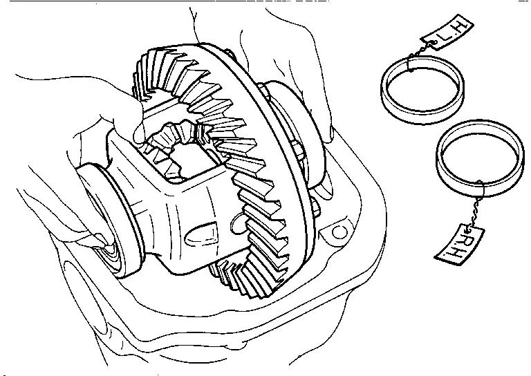
Remove differential assembly together with side bearing outer races and side bearing adjusting washers.
CAUTION:
Never drop the side bearing outer race.
Identify the assembled position of the side bearing outer race in advance.
Mark side bearing adjusting washers so that the original mounting positions (right/left) can be identified later.
Remove spacer.
Remove side bearing inner races, using puller (A) and the base (B).
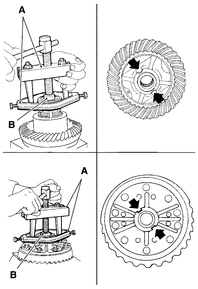
| A | : Puller [SST: ST33051001 (NI-22888-20)] |
| B | : Base [SST: ST33061000 (NI-8107-2)] |
CAUTION:
To prevent damage to the side bearing and drive gear, place copper plates between these parts and vise.
To prevent damage to bearing, engage puller jaws in groove (
 ).
).It is not necessary to remove side bearing inner race except when it is replaced.
For proper reinstallation, paint matching marks on one differential assembly and drive gear.
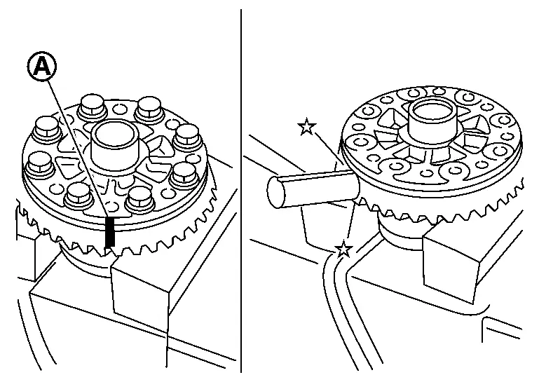
CAUTION:
For matching marks, use paint. Never damage differential assembly and drive gear.
Remove drive gear mounting bolts and then remove drive gear from differential assembly.
Perform inspection after disassembly. Refer to Inspection.
ASSEMBLY
Apply thread locking sealant into the thread hole of drive gear.
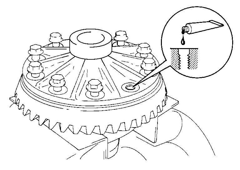
For applying thread locking sealant, refer to Exploded View.
CAUTION:
Clean and degrees drive gear back and threaded holes sufficiently.
Install the drive gear to differential assembly.
CAUTION:
Align the matching mark of differential assembly and drive gear.
Tighten the drive gear mounting bolts with the following procedure.Tighten the bolts in a crisscross fashion to the specified torque.
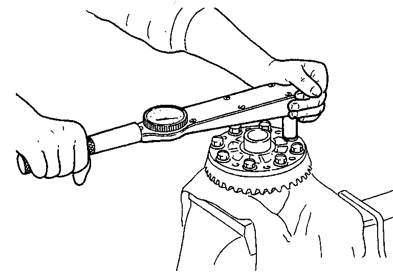
| Drive gear mounting bolt tightening torque | : 58.8 N·m (6.0 kg-m, 43 ft-lb) |
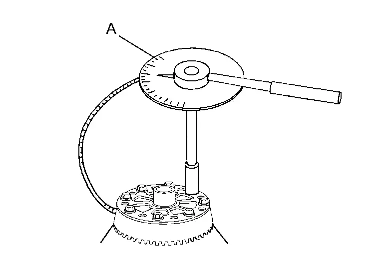
| Drive gear mounting bolt tightening angle | : 32 to 37 degree |
CAUTION:
Check the tightening angle using the angle wrench. Never make judgment by visual inspection.
Press side bearing inner races to differential assembly, using the drift (A) and the base (B).
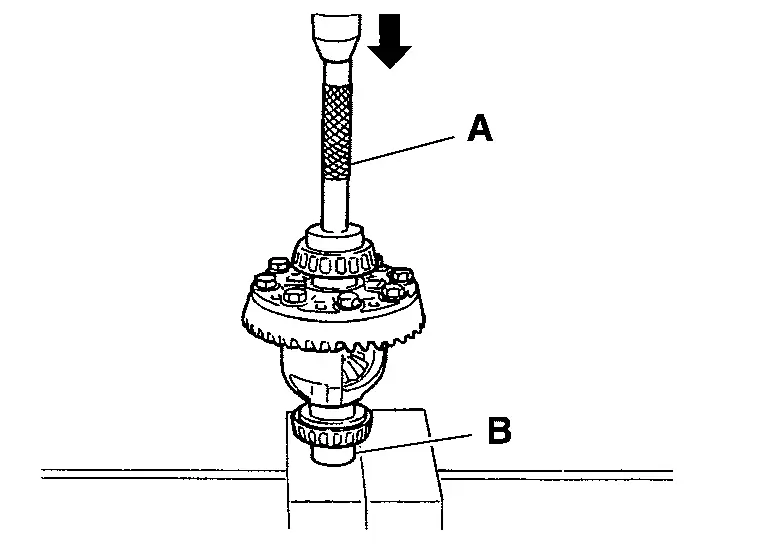
| A | : Drift [SST: ST33230000 (NI-35867)] |
| B | : Base [SST: ST33061000 (NI-8107-2)] |
CAUTION:
Never reuse side bearing inner race.
Install spacer.
Install the differential case assembly with the side bearing outer races into the gear carrier.
CAUTION:
Never reuse side bearing outer race when replacing side bearing inner race (replace as a set).
Insert left and right original side bearing adjusting washers in place between side bearings and gear carrier.
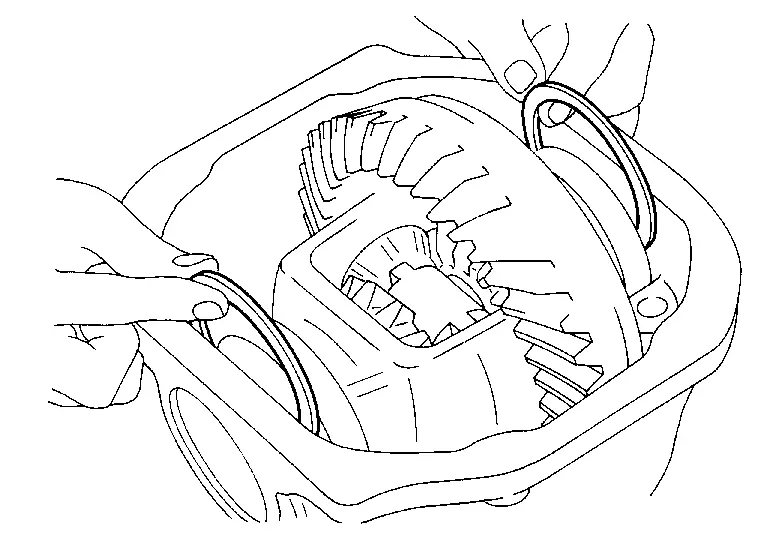
Install the side bearing caps with the matching marks aligned and tighten the side bearing cap bolts to the specified torque.
CAUTION:
Align matching marks on bearing cap with that on gear carrier.
Install side oil seal until it becomes flush with the gear carrier with the drift (A and B).
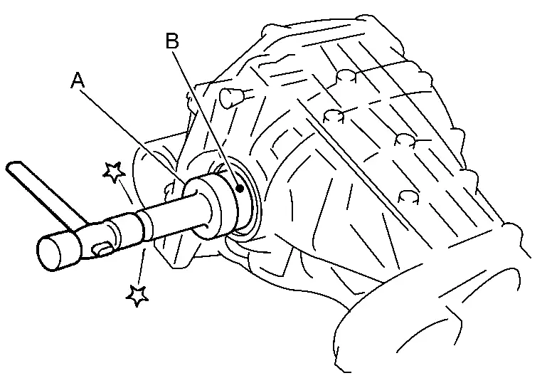
| A | : Drift [SST: ST30720000 (NI-25405)] |
| B | : Drift [SST: ST27863000 ( — )] |
CAUTION:
Never reuse side oil seal.
When installing, never incline oil seal.
Check that the oil seal lip is filled up with grease.
Check and adjust drive gear runout, tooth contact, backlash, and total preload torque. Refer to Adjustment.
Apply liquid gasket to mating surface of rear cover.
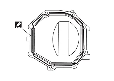
For applying liquid gasket, refer to Exploded View.
CAUTION:
Remove old gasket adhering to the mounting surfaces. Also remove any moisture, oil, or foreign material adhering to the mounting surfaces.
The width of sealant bead is approximately 3 mm (0.12 in). Apply sealant evenly.
Install the carrier cover to the gear carrier. Tighten the bolts to the specified torque.
For tightening torque, refer to Exploded View.
Install side shaft assembly. Refer to Disassembly and Assembly.
Install mounting insulators with drift [SST: ST33200000 (NI-26082)].
 Exploded View
Drive pinion lock nut Companion flange Front oil seal Pinion front bearing Collapsible spacer Gasket Filler plug Drain plug Mounting insulator Gear carrier Mounting insulator Breather con ...
 Adjustment
TOTAL PRELOAD TORQUE
Remove side shaft. Refer to Disassembly and Assembly.
Rotate drive pinion back and forth 2 to 3 times to check for unusual noise and rotation malfunction.
Rotate drive pinion at l ...
Other materials:
NVH Troubleshooting Chart
Use the chart below to find the cause of the symptom. If necessary, repair or replace these parts.
Possible cause and SUSPECTED PARTS Symptom Reference Vibration Shake Noise Uneven rotating torque × × Inspection Center bearing improper installation × × × — Excessive center bea ...
Commercial Service Tools
Tool name Description Drift
a: 61.0 mm (2.402 in) dia.
b: 56.3 mm (2.217 in) dia.
Installing front oil seal Drift
a: 66.3 mm (2.610 in) dia.
b: 61.9 mm (2.437 in) dia.
Installing rear oil seal Drift
a: 68.6 mm (2.701 in) dia.
b: 58.0 mm (2.283 in) dia.
Installing input oil seal Power tool
...
RADIATOR : Inspection
Check radiator for mud or clogging. If necessary, clean radiator as per the following:
Be careful not to bend or damage radiator fins.
When radiator is cleaned without removal, remove all surrounding parts such as radiator cooling fan assembly and horns. Then tape harness and connectors to prevent w ...

0.0065