
Nissan Armada 2025-2026 Service and Repair Manual: Adjustment
TOTAL PRELOAD TORQUE
Remove side shaft. Refer to Disassembly and Assembly.
Rotate drive pinion back and forth 2 to 3 times to check for unusual noise and rotation malfunction.
Rotate drive pinion at least 20 times to check for smooth operation of the bearing.
Measure total preload with the preload gauge (A) [SST: ST3127S000 (NI-25765-A)].
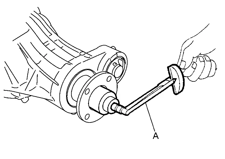
| Total preload torque | : Refer to Preload Torque. |
 NOTE:
NOTE:
Total preload torque = Pinion bearing preload torque + Side bearing preload torque
If measured value is out of the specification, disassemble it to check and adjust each part. Adjust the pinion bearing preload and side bearing preload.
Adjust the pinion bearing preload first, then adjust the side bearing preload.
When the preload torque is large  On pinion bearings: Replace the collapsible spacer.  On side bearings: Use thinner side bearing adjusting washers by the same amount to each side. For selecting adjusting washer, refer to the latest parts information. When the preload is small  On pinion bearings: Tighten the drive pinion lock nut.  On side bearings: Tighten side bearing adjusting nut.
Use thicker side bearing adjusting washers by the same amount to each side. For selecting adjusting washer, refer to the latest parts information.CAUTION:
Select a side bearing adjusting washer for right and left individually.
DRIVE GEAR RUNOUT
Remove carrier cover. Refer to Disassembly and Assembly.
Fit a dial indicator to the drive gear back face.
Rotate the drive gear to measure runout.
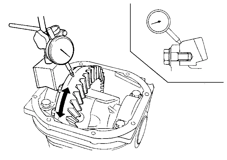
| Drive gear back face runout | : Refer to Drive Gear Runout. |
If the runout is outside of the repair limit, check drive gear assembly condition; foreign material may be caught between drive gear and differential case, or differential case or drive gear may be deformed, etc.
CAUTION:
Replace drive gear and drive pinion gear as a set.
TOOTH CONTACT
Remove carrier cover. Refer to Disassembly and Assembly.
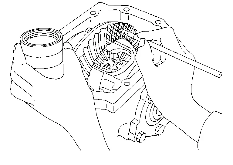
Apply red lead or equivalent to drive gear.
CAUTION:
Apply red lead or equivalent to both the faces of 3 to 4 gears at 4 locations evenly spaced on drive gear.
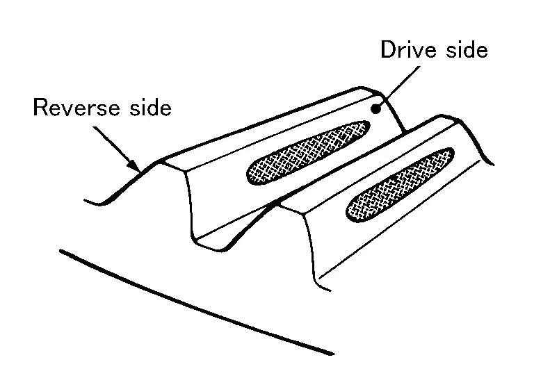
Rotate drive gear back and forth several times, check drive pinion gear to drive gear tooth contact.
CAUTION:
Check tooth contact on drive side and reverse side.
Tooth Contact Judgment Guide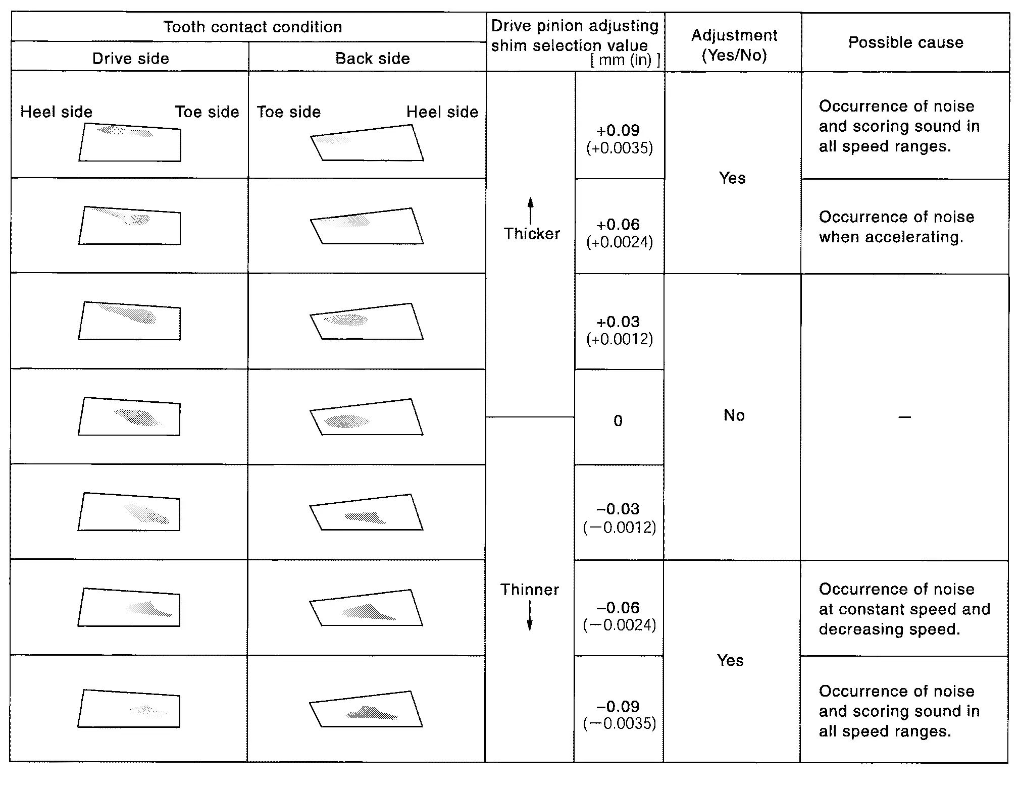
If tooth contact is improperly adjusted, follow the procedure below to adjust the pinion height (dimension X).
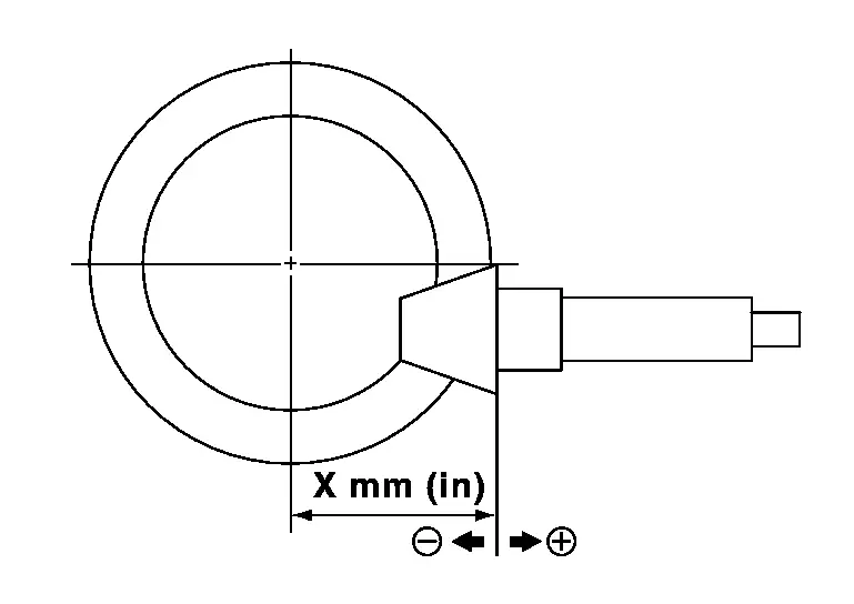
If the tooth contact is near the face (face contact), or near the heel (heel contact), thicken pinion height adjusting washer to move drive pinion closer to drive gear.
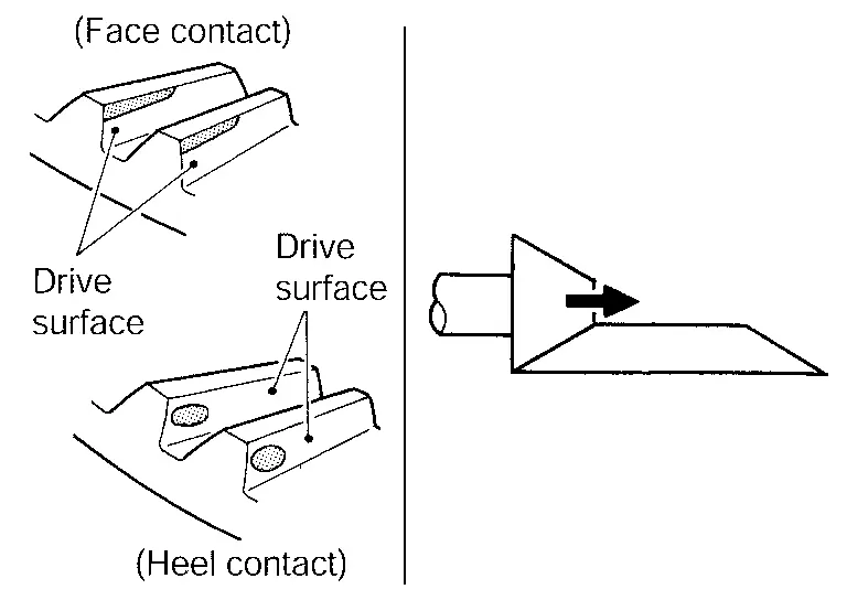
For selecting adjusting washer, refer to the latest parts information.
If the tooth contact is near the flank (flank contact), or near the toe (toe contact), thin pinion height adjusting washer to move drive pinion farther from drive gear.
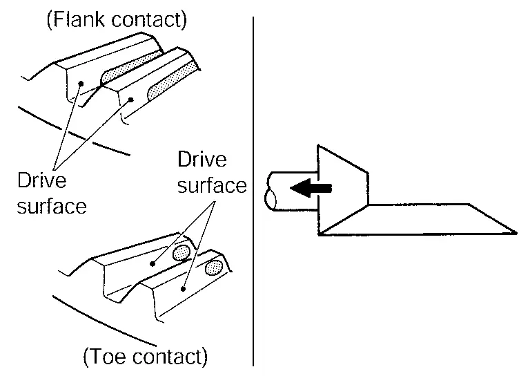
For selecting adjusting washer, refer to the latest parts information.
BACKLASH
Remove carrier cover. Refer to Disassembly and Assembly.
Fit a dial indicator to the drive gear face to measure the backlash.
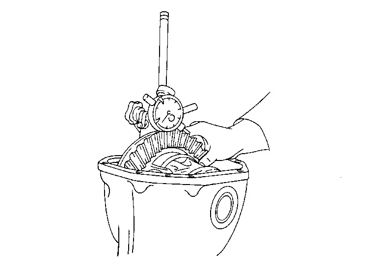
| Backlash | : Refer to Backlash. |
If the backlash is outside of the specified value, adjust with the side bearing adjusting nut.
When the backlash is large: Make drive gear back side adjusting washer thicker, and drive gear tooth side adjusting washer thinner by the same amount. For selecting adjusting washer, refer to the latest parts information. When the backlash is small: Make drive gear back side adjusting washer thinner, and drive gear tooth side adjusting washer thicker by the same amount. For selecting adjusting washer, refer to the latest parts information. CAUTION:
Never change the total amount of washers as it changes the bearing preload.
 Disassembly and Assembly
DISASSEMBLY
Remove mounting insulators with drift [SST: ST33200000 (NI-26082)] if necessary.
Remove side shaft assembly. Refer to Disassembly and Assembly.
Remove side oil seal from gear carrier with ...
 Inspection
INSPECTION AFTER DISASSEMBLY
Drive Gear and Drive Pinion
Clean up the disassembled parts.
If the gear teeth never mesh or line-up correctly, determine the cause and adjust or replace as necessary.
If ...
Other materials:
Exploded View
WITHOUT ELECTRIC MOTOR
Steering column assembly Upper joint : N·m (kg-m, ft-lb)
WITH ELECTRIC MOTOR
Steering column assembly Upper joint : N·m (kg-m, ft-lb) ...
Inspection
INSPECTION AFTER REMOVAL
Replace the shims and shim covers if rust is excessively attached.
Eliminate rust on the return spring, pad retainers and the torque member. Replace them if rust is excessively attached.
INSPECTION AFTER INSTALLATION
Check a drag of front disc brake. If any drag is found, f ...
Work Procedure
INSPECTION START
Check service records for any recent repairs that may indicate a related malfunction, or a current need for scheduled maintenance.
Open engine hood and check the following:
Harness connectors for improper connections
Wiring harness for improper connections, pinches and cut
Vacuum h ...

0.0075