Exploded View
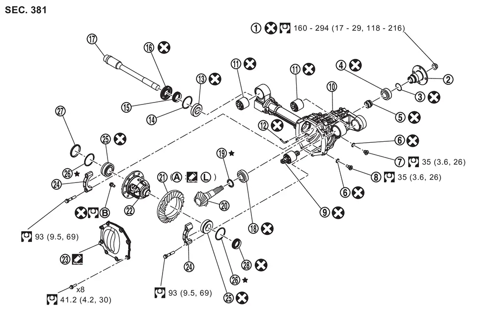
 |
Drive pinion lock nut |  |
Companion flange |  |
Front oil seal |
 |
Pinion front bearing |  |
Collapsible spacer |  |
Gasket |
 |
Filler plug |  |
Drain plug |  |
Mounting insulator |
 |
Gear carrier |  |
Mounting insulator |  |
Breather connector |
 |
Side shaft bearing |  |
Snap ring |  |
Snap ring |
 |
Side oil seal |  |
Side shaft |  |
Pinion rear bearing |
 |
Pinion height adjusting washer |  |
Drive pinion |  |
Drive gear |
 |
Differential assembly |  |
Carrier cover |  |
Bearing cap |
 |
Side bearing |  |
Side bearing adjusting washer |  |
Spacer |
 |
Side oil seal | ||||
 |
Screw hole |  |
Comply with the assembly procedure when tightening. Refer to Disassembly and Assembly. | ||
 : N·m (kg-m, ft-lb) : N·m (kg-m, ft-lb) |
|||||
 : Always replace after every disassembly. : Always replace after every disassembly. |
|||||
 : Select with proper thickness. : Select with proper thickness. |
|||||
 : Apply Genuine Liquid Gasket, Three Bond 1217 or equivalent. Refer to Recommended Chemical Products and Sealants. : Apply Genuine Liquid Gasket, Three Bond 1217 or equivalent. Refer to Recommended Chemical Products and Sealants. |
|||||
 : Apply Genuine High Strength Thread Locking Sealant, Loctite 270 or equivalent. Refer to Recommended Chemical Products and Sealants. : Apply Genuine High Strength Thread Locking Sealant, Loctite 270 or equivalent. Refer to Recommended Chemical Products and Sealants. |
|||||
Disassembly and Assembly
DISASSEMBLY
Remove side shaft assembly. Refer to Disassembly and Assembly.
Remove differential assembly. Refer to Disassembly and Assembly.
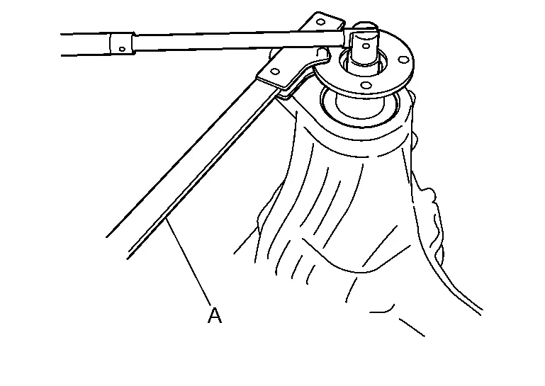
While holding companion flange with the flange wrench (A) (commercial service tool), remove drive pinion lock nut.
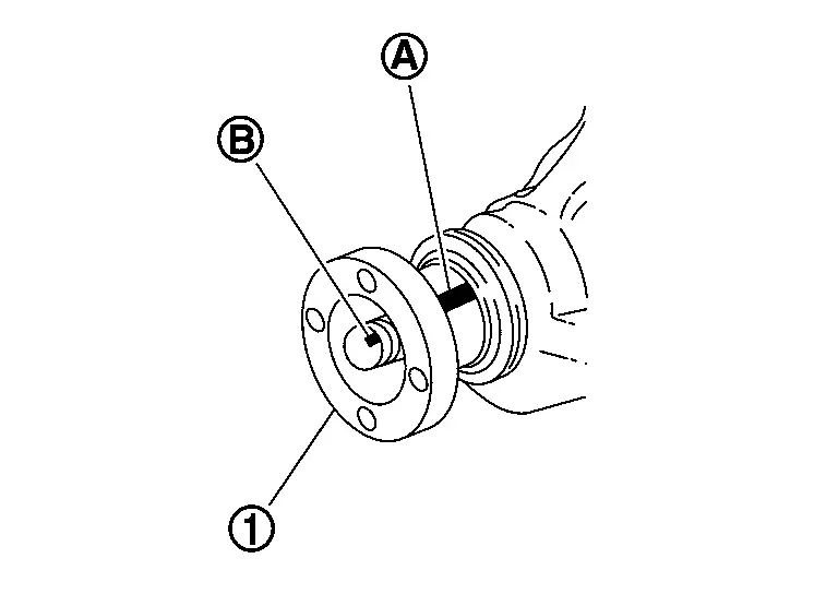
Put matching mark on the end of drive pinion. The matching mark should be in line with the matching mark on companion flange .
CAUTION:
For matching mark, use paint. Never damage companion flange and drive pinion.
 NOTE:
NOTE:
The matching mark on the final drive companion flange indicates the maximum vertical runout position.
When replacing companion flange, matching mark is not necessary.
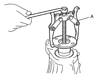
Remove companion flange using the suitable puller (A) (commercial service tool).
Press drive pinion assembly and remove it.
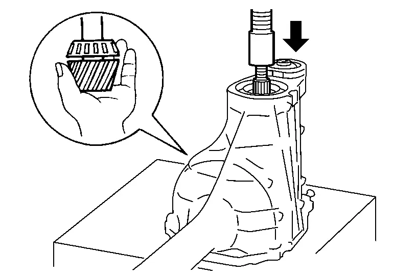
CAUTION:
Never drop drive pinion assembly.
Remove front oil seal, using oil seal remover (A) (commercial service tool).
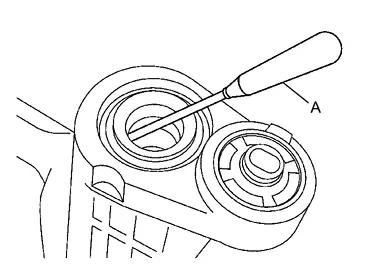
CAUTION:
Never damage carrier case.
Remove pinion front bearing inner race.
Remove collapsible spacer.
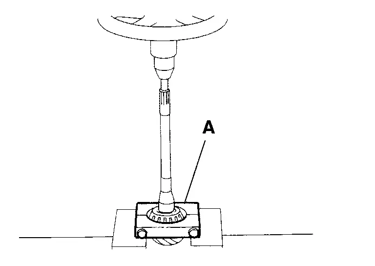
Remove pinion rear bearing inner race and pinion height adjusting washer with the separator (A) (commercial service tool).
Tap pinion front bearing outer race and rear bearing outer race uniformly using a brass rod or equivalent to remove them.
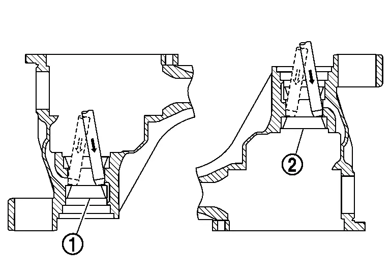
CAUTION:
Never damage carrier case.
Perform inspection after disassembly. Refer to Inspection.
ASSEMBLY
Install pinion front bearing outer race using drift (A) [SST: KV38100200 (NI-26233)].
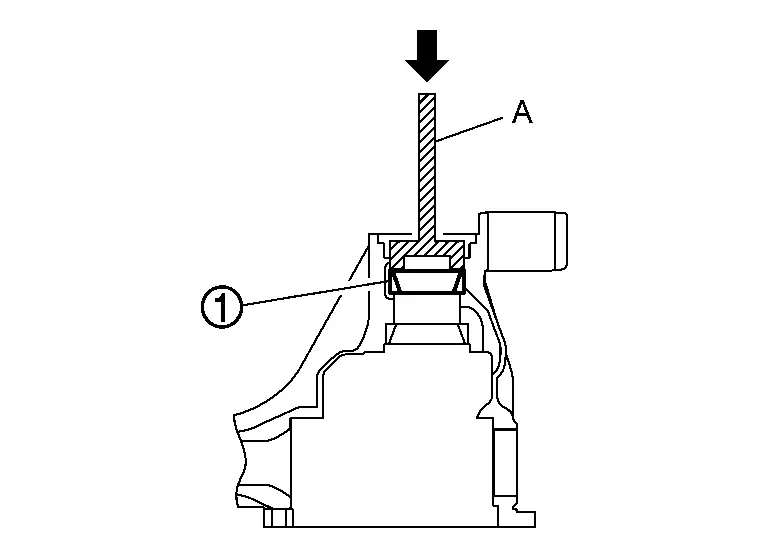
CAUTION:
-
At first, using a hammer, tap bearing outer race until it becomes flat to carrier case.
-
Never reuse pinion front bearing outer race.
Install pinion rear bearing outer race using drift (A) and drift bar (B).
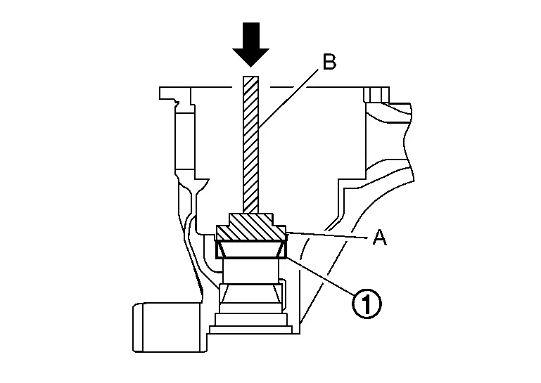
| A | : Drift [SST: ST30613000 (NI-25742-3)] |
| B | : Drift bar [SST: ST30611000 (NI-25742-1)] |
CAUTION:
-
At first, using a hammer, tap bearing outer race until it becomes flat to carrier case.
-
Never reuse pinion rear bearing outer race.
Temporarily install pinion height adjusting washer .
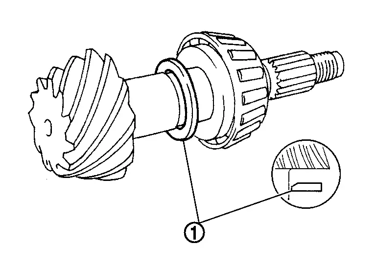
CAUTION:
Pay attention to the direction of pinion height adjusting washer. (Assemble as shown in the figure.)
When hypoid gear set has been replaced
-
Select pinion height adjusting washer. Refer to Adjustment.
When hypoid gear set has been reused
-
Temporarily install the removed pinion height adjusting washer or same thickness washer to drive pinion.
Install pinion rear bearing inner race to drive pinion with the drift (A) [SST: ST30901000 (NI-26010-01)].
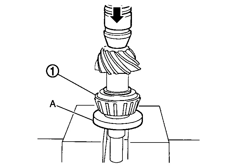
CAUTION:
Never reuse pinion rear bearing inner race.
Check and adjust the tooth contact and backlash of drive gear and drive pinion following the procedure below. Assemble drive pinion into carrier case.
CAUTION:
Never assemble collapsible spacer.
Assemble pinion front bearing inner race to drive pinion assembly.CAUTION:
Never reuse pinion front bearing inner race.
Using drift (A) [SST: ST33200000 (NI-26082)], press the pinion front bearing inner race to drive pinion as far as drive pinion lock nut can be tightened.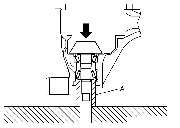
CAUTION:
Never assemble front oil seal.
NOTE:
When reusing drive pinion, align the matching mark of drive pinion with the matching mark of companion flange, and then install companion flange .
NOTE:
Use removed drive pinion lock nut only for the preload measurement.
Rotate drive pinion more than 20 times to adjust bearing. Tighten to drive pinion lock nut holding companion flange with the flange wrench (A) (commercial service tool), while adjusting pinion bearing preload torque using preload gauge (B) [SST: ST3127S000 (NI-25765-A)].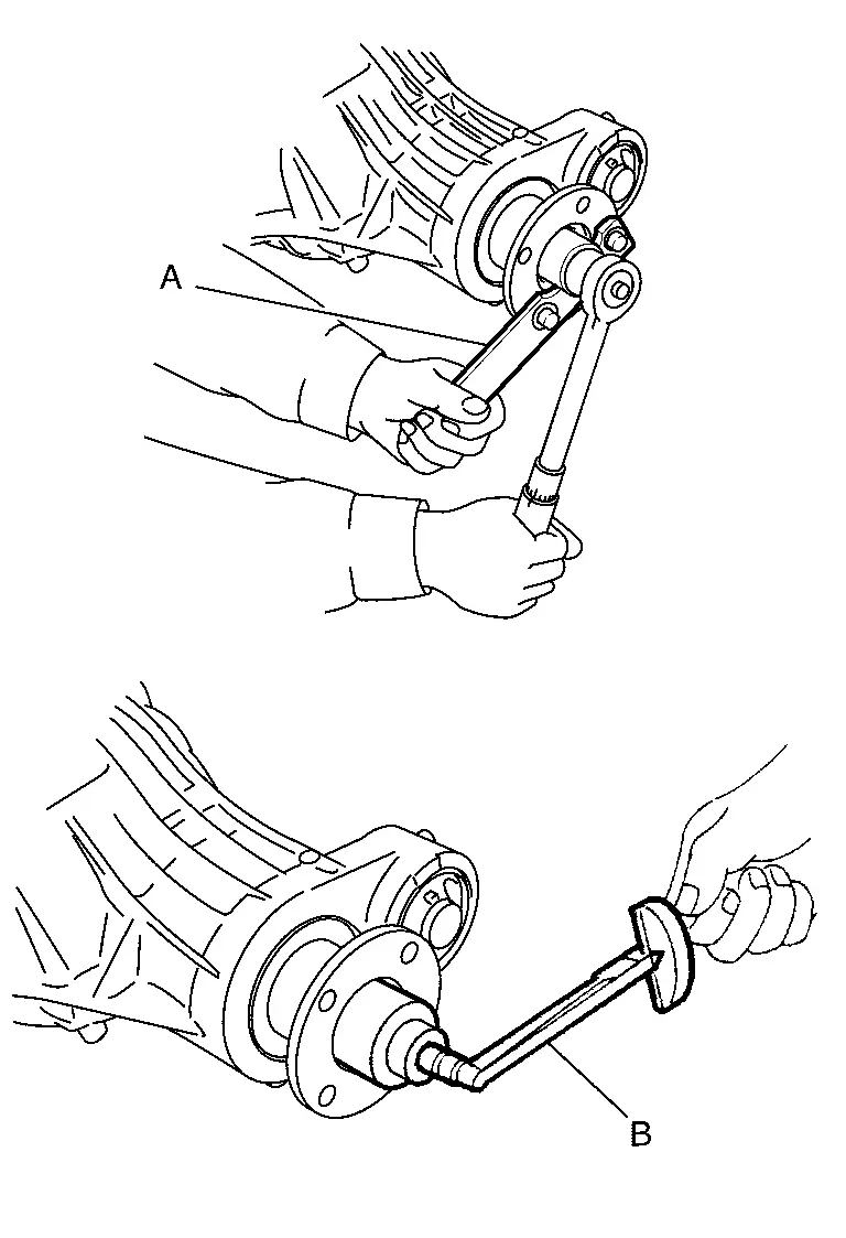
|
Pinion bearing preload (without oil seal) |
: 1.08 - 1.66 N·m (0.11 –0.16 kg-m, 10 –14 in-lb) |
CAUTION:
Drive pinion lock nut is tightened with no collapsible spacer. Be careful not to overtighten it. While measuring the preload, tighten it by 5° to 10°.
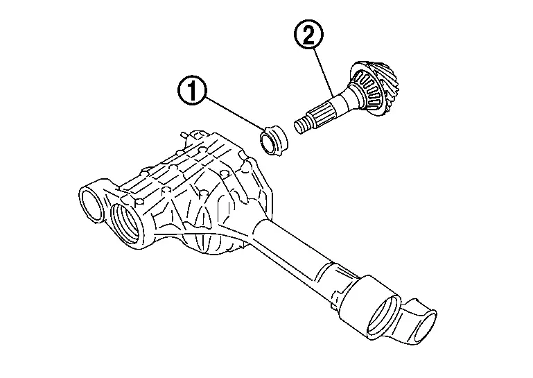
Assemble removed side bearing adjusting washer or same thickness of it and install differential assembly. Refer to Disassembly and Assembly. Install bearing caps. Check and adjust tooth contact, drive gear to drive pinion backlash. Refer to Adjustment. Remove bearing caps and differential assembly. Remove companion flange. Remove drive pinion assembly from gear carrier. Remove pinion front bearing inner race.Assemble collapsible spacer to drive pinion .
CAUTION:
Never reuse collapsible spacer.
Assemble drive pinion into carrier case.
Assemble pinion front bearing inner race to drive pinion assembly.
CAUTION:
Never reuse pinion front bearing inner race.
Using drift (A) [SST: ST33200000 (NI-26082)], press the pinion front bearing inner race to drive pinion as far as drive pinion nut can be tightened.
Install front oil seal until it becomes flush with the carrier case end, using the drifts (A and B) as shown in figure.
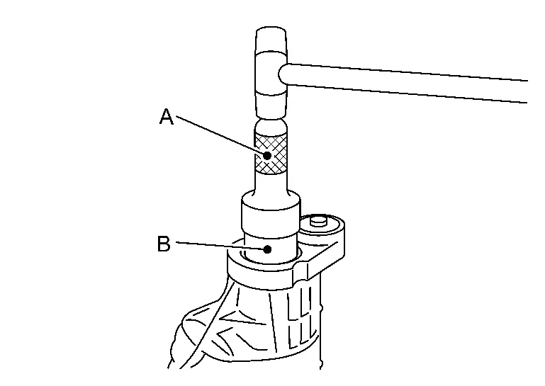
| A | : Drift [SST: ST30720000 (NI-25405)] |
| B | : Drift [SST: ST27863000 ( — )] |
CAUTION:
-
Never reuse oil seal.
-
When installing, never incline oil seal.
-
Check that the oil seal lip is filled up with grease.
Install companion flange.
NOTE:
When reusing drive pinion, align the matching mark of drive pinion with the matching mark of companion flange, and then install companion flange .
Temporarily tighten drive pinion lock nut to drive pinion.
CAUTION:
Never reuse drive pinion lock nut.
While holding companion flange with the flange wrench (A) (commercial service tool), tighten drive pinion lock nut within the limits of specified torque so as to keep the pinion bearing preload within a standard values, using preload gauge (B) [SST: ST3127S000 (NI-25765-A)].
| Pinion bearing preload | : Refer to Preload Torque. |
CAUTION:
-
Adjust to the lower limit of the drive pinion lock nut tightening torque first.
-
If the preload torque exceeds the specified value, replace collapsible spacer and tighten it again to adjust. Never loosen drive pinion lock nut to adjust the preload torque.
-
After adjustment, rotate drive pinion back and forth 2 to 3 times to check for unusual noise, rotation malfunction, and other malfunctions.
Install differential assembly. Refer to Disassembly and Assembly.
CAUTION:
Never install carrier cover yet.
Check and adjust drive gear runout, tooth contact, and drive gear to drive pinion backlash. Refer to Adjustment.
Check companion flange runout. Refer to Adjustment.
Check total preload torque. Refer to Adjustment.
Install side shaft assembly. Refer to Disassembly and Assembly.
Install carrier cover. Refer to Disassembly and Assembly.
Adjustment
PINION GEAR HEIGHT
If the hypoid gear set has been replaced, select the pinion height adjusting washer.
Use the formula below to calculate pinion height adjusting washer thickness.
| Washer selection equation: | |||
| T = T0 + (t1− t2) | |||
| T: | Correct washer thickness | ||
| T0: | Removed washer thickness | ||
| t1: |
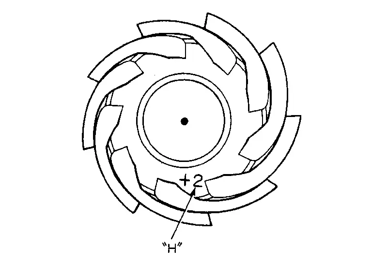
Old drive pinion head letter “H × 0.01” (“H”: machined tolerance 1/100 mm × 100) |
||
| t2: |
New drive pinion head letter “H × 0.01” (“H”: machined tolerance 1/100 mm × 100) |
||
| Example: | |||
| T = 3.21 + [(2 × 0.01) − (−1 × 0.01)] = 3.24 | |||
| T0: | 3.21 | ||
| t1: | +2 | ||
| t2: | −1 | ||
Select the proper pinion height adjusting washer. For selecting adjusting washer, refer to the latest parts information.
CAUTION:
If unable to find a washer of desired thickness, use a washer with thickness closest to the calculated value.
| Example: | ||
| Calculated value... T = 3.22 mm | ||
| Used washer... T = 3.21 mm | ||
COMPANION FLANGE RUNOUT
Fit a dial indicator onto the companion flange face (inner side of the propeller shaft mounting bolt holes).
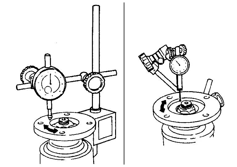
Rotate companion flange to check for runout.
| Companion flange face runout | : Refer to Companion Flange Runout. |
Fit a test indicator to the inner side of companion flange (socket diameter).
Rotate companion flange to check for runout.
| Inner side of the companion flange runout | : Refer to Companion Flange Runout. |
If the runout value is outside the runout limit, follow the procedure below to adjust.Check for runout while changing the phase between companion flange and drive pinion by 90° step, and search for the position where the runout is the minimum. If the runout value is still outside of the limit after the phase has been changed, possible cause will be an assembly malfunction of drive pinion and pinion bearing and malfunction of pinion bearing. Check for these items and repair if necessary. If the runout value is still outside of the limit after the check and repair, replace companion flange.
Inspection
INSPECTION AFTER DISASSEMBLY
Drive Gear and Drive Pinion
-
Clean up the disassembled parts.
-
If the gear teeth never mesh or line-up correctly, determine the cause and adjust or replace as necessary.
-
If the gears are worn, cracked, damaged, pitted or chipped (by friction) noticeably, replace with new drive gear and drive pinion as a set.
Oil Seal
-
Whenever disassembled, replace.
-
If wear, deterioration of adherence (sealing force lips), or damage is detected on the lips, replace them.
Companion Flange
-
Clean up the disassembled parts.
-
If any chipped mark [about 0.1 mm, (0.004 in)] or other damage on the contact sides of the lips of the companion flange is found, replace.
Carrier Case
-
If any wear or crack on the sliding surface of the carrier case is found, replace.
Other materials
Roof Rear Garnish
Removal and Installation
CAUTION:
Never damage the roof panel.REMOVALCAUTION:
When removing, always use a remover tool that is made of plastic to prevent damage to the parts.Fully open back door.
Release roof rear garnish portion of back door weather-strip. Refer to Removal and Installation.
Release ...
Rear Bumper
Exploded View
Rear bumper side bracket LH
Rear bumper bracket RH
Rear bumper bracket LH
Hands free sensor bracket
(with hands free sensor models)
Double-sided tape
[t: 1.2 mm (0.047 in)]
(with hands free sensor models)
Rear bumper fascia
Rear bumper molding LH
Rear bumper fi ...
Engine Under Cover
Exploded View
Engine under cover front
Engine under cover rear
N·m (kg-m, ft-lb)
Removal and Installation
WARNING:
REMOVALRemove mounting bolts, and then remove engine under cover rear.
Remove mounting bolts, and then remove engine under cover front.INSTALLATIONInst ...