Exploded View
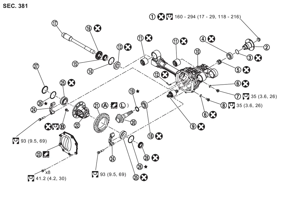
 |
Drive pinion lock nut |  |
Companion flange |  |
Front oil seal |
 |
Pinion front bearing |  |
Collapsible spacer |  |
Gasket |
 |
Filler plug |  |
Drain plug |  |
Mounting insulator |
 |
Gear carrier |  |
Mounting insulator |  |
Breather connector |
 |
Side shaft bearing |  |
Snap ring |  |
Snap ring |
 |
Side oil seal |  |
Side shaft |  |
Pinion rear bearing |
 |
Pinion height adjusting washer |  |
Drive pinion |  |
Drive gear |
 |
Differential assembly |  |
Carrier cover |  |
Bearing cap |
 |
Side bearing |  |
Side bearing adjusting washer |  |
Spacer |
 |
Side oil seal | ||||
 |
Screw hole |  |
Comply with the assembly procedure when tightening. Refer to Disassembly and Assembly. | ||
 : N·m (kg-m, ft-lb) : N·m (kg-m, ft-lb) |
|||||
 : Always replace after every disassembly. : Always replace after every disassembly. |
|||||
 : Select with proper thickness. : Select with proper thickness. |
|||||
 : Apply Genuine Liquid Gasket, Three Bond 1217 or equivalent. Refer to Recommended Chemical Products and Sealants. : Apply Genuine Liquid Gasket, Three Bond 1217 or equivalent. Refer to Recommended Chemical Products and Sealants. |
|||||
 : Apply Genuine High Strength Thread Locking Sealant, Loctite 270 or equivalent. Refer to Recommended Chemical Products and Sealants. : Apply Genuine High Strength Thread Locking Sealant, Loctite 270 or equivalent. Refer to Recommended Chemical Products and Sealants. |
|||||
Disassembly and Assembly
DISASSEMBLY
Remove mounting insulators with drift [SST: ST33200000 (NI-26082)] if necessary.
Remove side shaft assembly. Refer to Disassembly and Assembly.
Remove side oil seal from gear carrier with a oil seal remover (commercial service tool).
For proper reinstallation, paint matching marks on one side of bearing cap.
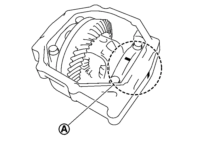
CAUTION:
-
For matching marks, use paint. Never damage bearing caps and carrier case.
-
Bearing caps are manufactured as integral molding. Use the matching marks to them in their original positions.
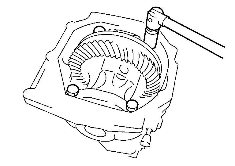
Remove bearing caps.
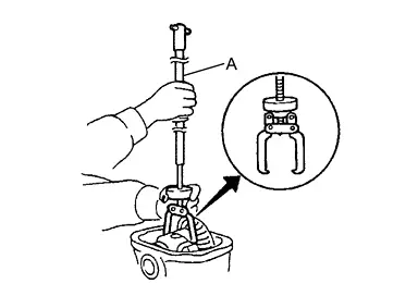
Lift the differential assembly out of the gear carrier with sliding hammer (A) (commercial service tool).
Remove differential assembly together with side bearing outer races and side bearing adjusting washers.
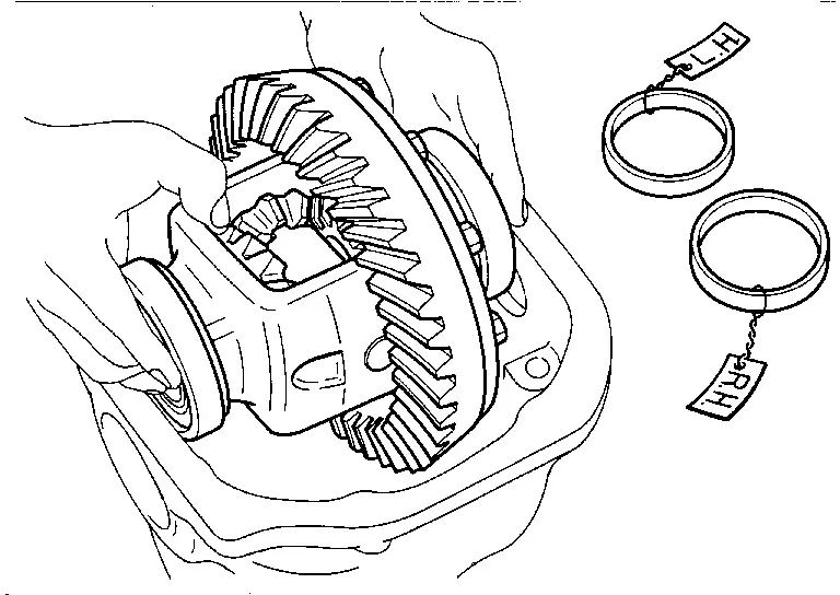
CAUTION:
-
Never drop the side bearing outer race.
-
Identify the assembled position of the side bearing outer race in advance.
-
Mark side bearing adjusting washers so that the original mounting positions (right/left) can be identified later.
Remove spacer.
Remove side bearing inner races, using puller (A) and the base (B).
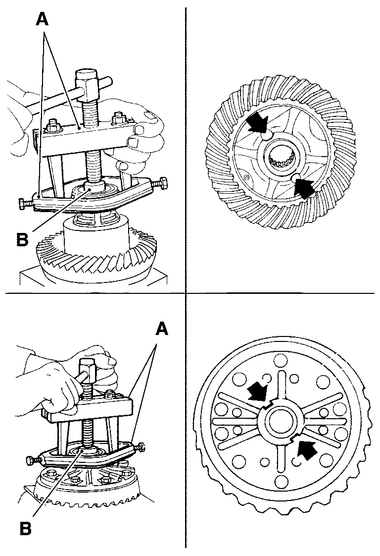
| A | : Puller [SST: ST33051001 (NI-22888-20)] |
| B | : Base [SST: ST33061000 (NI-8107-2)] |
CAUTION:
-
To prevent damage to the side bearing and drive gear, place copper plates between these parts and vise.
-
To prevent damage to bearing, engage puller jaws in groove (
 ).
). -
It is not necessary to remove side bearing inner race except when it is replaced.
For proper reinstallation, paint matching marks on one differential assembly and drive gear.
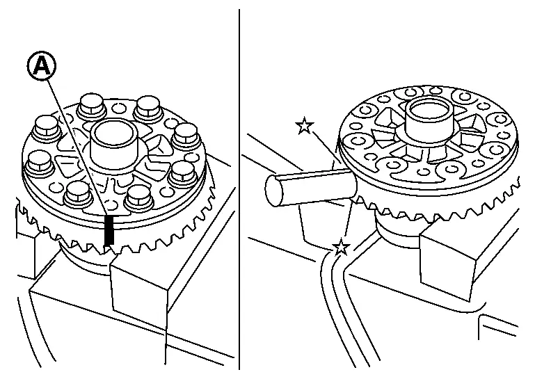
CAUTION:
For matching marks, use paint. Never damage differential assembly and drive gear.
Remove drive gear mounting bolts and then remove drive gear from differential assembly.
Perform inspection after disassembly. Refer to Inspection.
ASSEMBLY
Apply thread locking sealant into the thread hole of drive gear.
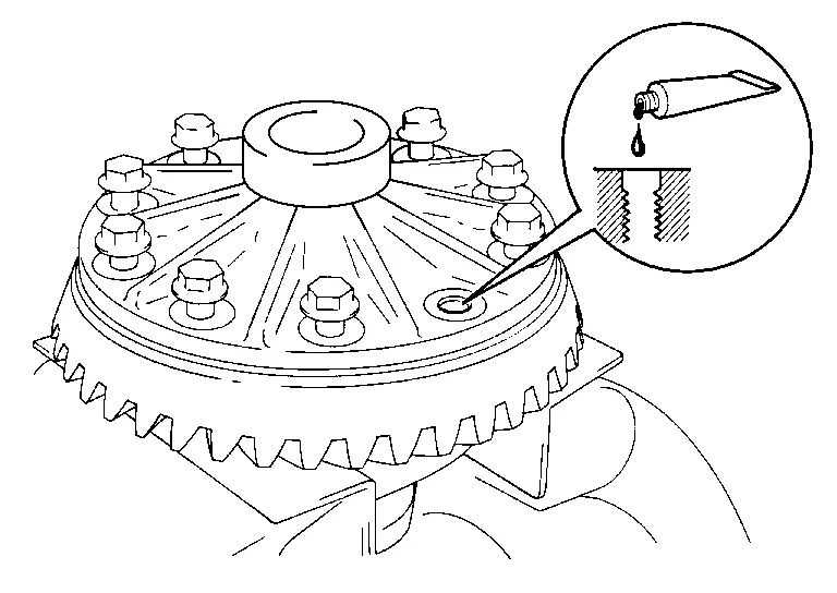
-
For applying thread locking sealant, refer to Exploded View.
CAUTION:
Clean and degrees drive gear back and threaded holes sufficiently.
Install the drive gear to differential assembly.
CAUTION:
Align the matching mark of differential assembly and drive gear.
Tighten the drive gear mounting bolts with the following procedure.Tighten the bolts in a crisscross fashion to the specified torque.
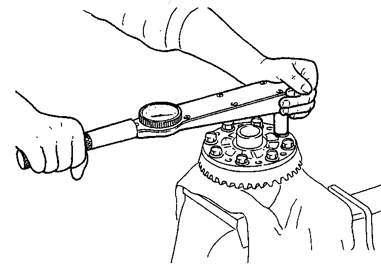
| Drive gear mounting bolt tightening torque | : 58.8 N·m (6.0 kg-m, 43 ft-lb) |
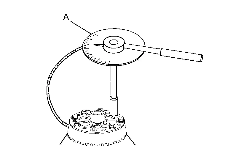
| Drive gear mounting bolt tightening angle | : 32 to 37 degree |
CAUTION:
Check the tightening angle using the angle wrench. Never make judgment by visual inspection.
Press side bearing inner races to differential assembly, using the drift (A) and the base (B).
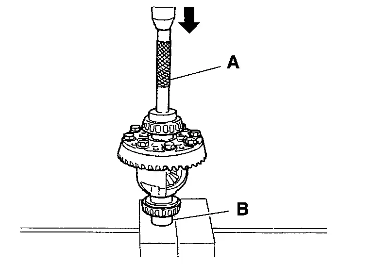
| A | : Drift [SST: ST33230000 (NI-35867)] |
| B | : Base [SST: ST33061000 (NI-8107-2)] |
CAUTION:
Never reuse side bearing inner race.
Install spacer.
Install the differential case assembly with the side bearing outer races into the gear carrier.
CAUTION:
Never reuse side bearing outer race when replacing side bearing inner race (replace as a set).
Insert left and right original side bearing adjusting washers in place between side bearings and gear carrier.
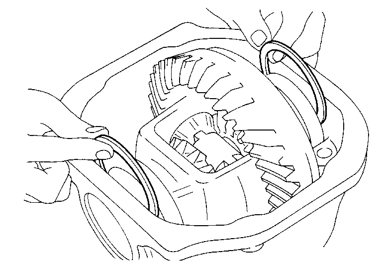
Install the side bearing caps with the matching marks aligned and tighten the side bearing cap bolts to the specified torque.
CAUTION:
Align matching marks on bearing cap with that on gear carrier.
Install side oil seal until it becomes flush with the gear carrier with the drift (A and B).
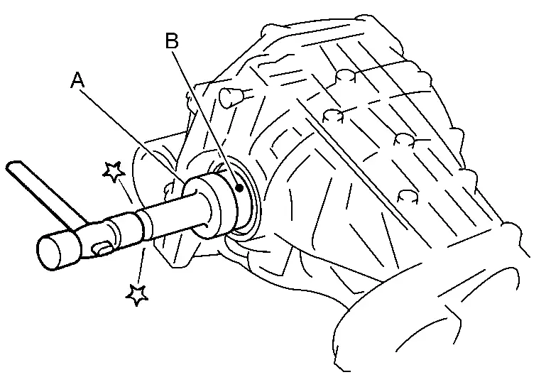
| A | : Drift [SST: ST30720000 (NI-25405)] |
| B | : Drift [SST: ST27863000 ( — )] |
CAUTION:
-
Never reuse side oil seal.
-
When installing, never incline oil seal.
-
Check that the oil seal lip is filled up with grease.
Check and adjust drive gear runout, tooth contact, backlash, and total preload torque. Refer to Adjustment.
Apply liquid gasket to mating surface of rear cover.
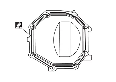
-
For applying liquid gasket, refer to Exploded View.
CAUTION:
-
Remove old gasket adhering to the mounting surfaces. Also remove any moisture, oil, or foreign material adhering to the mounting surfaces.
-
The width of sealant bead is approximately 3 mm (0.12 in). Apply sealant evenly.
Install the carrier cover to the gear carrier. Tighten the bolts to the specified torque.
-
For tightening torque, refer to Exploded View.
Install side shaft assembly. Refer to Disassembly and Assembly.
Install mounting insulators with drift [SST: ST33200000 (NI-26082)].
Adjustment
TOTAL PRELOAD TORQUE
Remove side shaft. Refer to Disassembly and Assembly.
Rotate drive pinion back and forth 2 to 3 times to check for unusual noise and rotation malfunction.
Rotate drive pinion at least 20 times to check for smooth operation of the bearing.
Measure total preload with the preload gauge (A) [SST: ST3127S000 (NI-25765-A)].
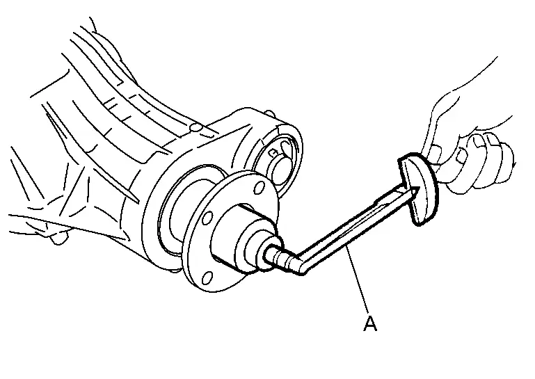
| Total preload torque | : Refer to Preload Torque. |
 NOTE:
NOTE:
Total preload torque = Pinion bearing preload torque + Side bearing preload torque
-
If measured value is out of the specification, disassemble it to check and adjust each part. Adjust the pinion bearing preload and side bearing preload.
Adjust the pinion bearing preload first, then adjust the side bearing preload.
When the preload torque is large On pinion bearings: Replace the collapsible spacer. On side bearings: Use thinner side bearing adjusting washers by the same amount to each side. For selecting adjusting washer, refer to the latest parts information. When the preload is small On pinion bearings: Tighten the drive pinion lock nut. On side bearings: Tighten side bearing adjusting nut.
Use thicker side bearing adjusting washers by the same amount to each side. For selecting adjusting washer, refer to the latest parts information.CAUTION:
Select a side bearing adjusting washer for right and left individually.
DRIVE GEAR RUNOUT
Remove carrier cover. Refer to Disassembly and Assembly.
Fit a dial indicator to the drive gear back face.
Rotate the drive gear to measure runout.
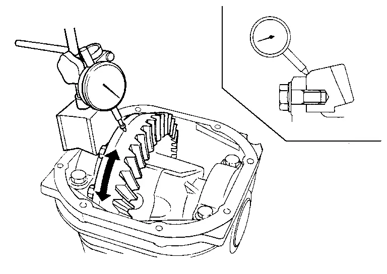
| Drive gear back face runout | : Refer to Drive Gear Runout. |
-
If the runout is outside of the repair limit, check drive gear assembly condition; foreign material may be caught between drive gear and differential case, or differential case or drive gear may be deformed, etc.
CAUTION:
Replace drive gear and drive pinion gear as a set.
TOOTH CONTACT
Remove carrier cover. Refer to Disassembly and Assembly.
Apply red lead or equivalent to drive gear.
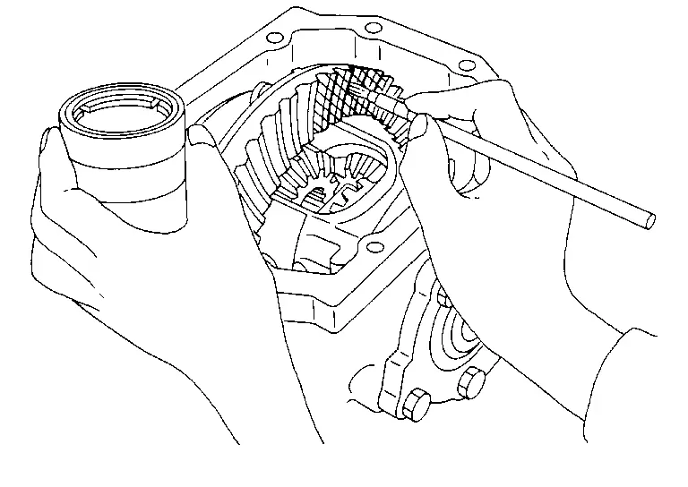
CAUTION:
Apply red lead or equivalent to both the faces of 3 to 4 gears at 4 locations evenly spaced on drive gear.
Rotate drive gear back and forth several times, check drive pinion gear to drive gear tooth contact.
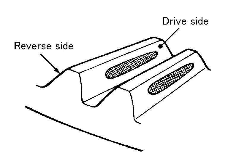
CAUTION:
Check tooth contact on drive side and reverse side.
Tooth Contact Judgment Guide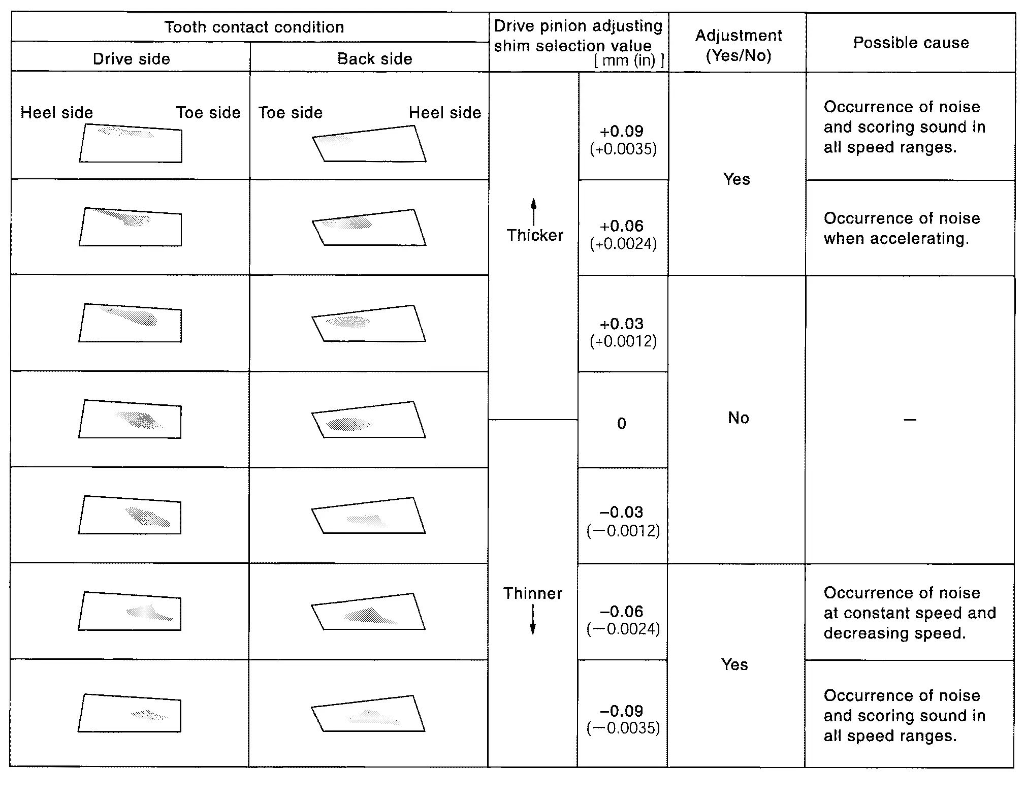
If tooth contact is improperly adjusted, follow the procedure below to adjust the pinion height (dimension X).
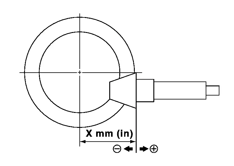
-
If the tooth contact is near the face (face contact), or near the heel (heel contact), thicken pinion height adjusting washer to move drive pinion closer to drive gear.
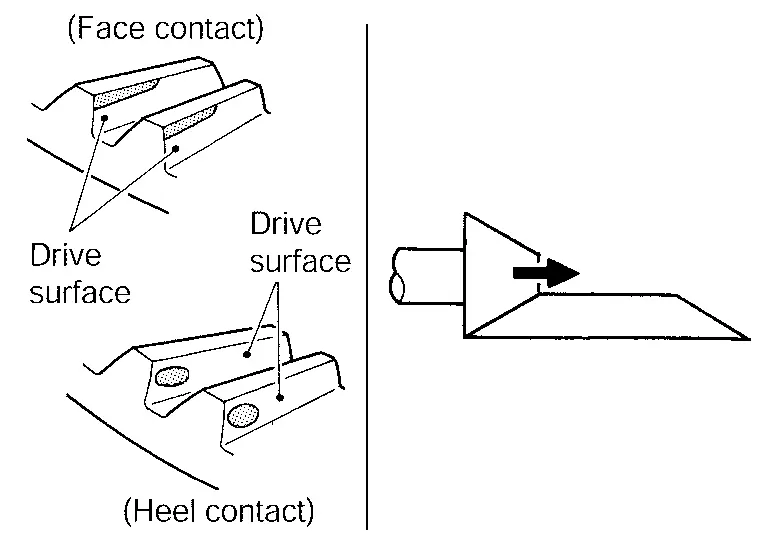
For selecting adjusting washer, refer to the latest parts information.
-
If the tooth contact is near the flank (flank contact), or near the toe (toe contact), thin pinion height adjusting washer to move drive pinion farther from drive gear.
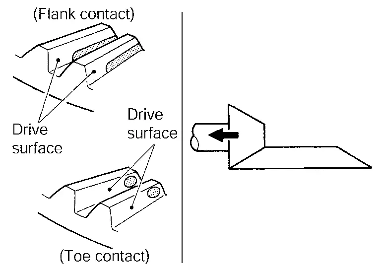
For selecting adjusting washer, refer to the latest parts information.
BACKLASH
Remove carrier cover. Refer to Disassembly and Assembly.
Fit a dial indicator to the drive gear face to measure the backlash.
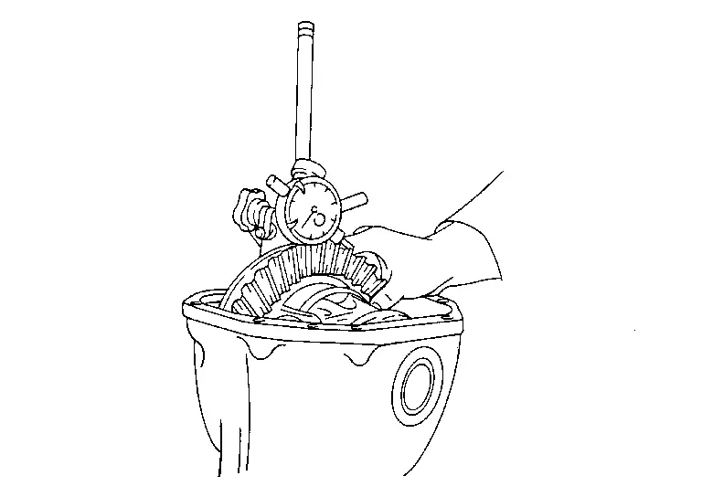
| Backlash | : Refer to Backlash. |
-
If the backlash is outside of the specified value, adjust with the side bearing adjusting nut.
When the backlash is large: Make drive gear back side adjusting washer thicker, and drive gear tooth side adjusting washer thinner by the same amount. For selecting adjusting washer, refer to the latest parts information. When the backlash is small: Make drive gear back side adjusting washer thinner, and drive gear tooth side adjusting washer thicker by the same amount. For selecting adjusting washer, refer to the latest parts information. CAUTION:
Never change the total amount of washers as it changes the bearing preload.
Inspection
INSPECTION AFTER DISASSEMBLY
Drive Gear and Drive Pinion
-
Clean up the disassembled parts.
-
If the gear teeth never mesh or line-up correctly, determine the cause and adjust or replace as necessary.
-
If the gears are worn, cracked, damaged, pitted or chipped (by friction) noticeably, replace with new drive gear and drive pinion as a set.
Oil Seal
-
Whenever disassembled, replace.
-
If wear, deterioration of adherence (sealing force lips), or damage is detected on the lips, replace them.
Differential Assembly
-
Clean up the disassembled parts.
-
If any wear or crack is found, replace.
Other materials
Intelligent Key operating range
The Nissan Armada Intelligent Key system functions only when the key is located
within the defined operating range of the request switches 1 and 2 (if equipped).
For optimal performance, the Nissan Armada Intelligent Key must be within approximately
80 cm (31.50 in) of each request switch.
...
A/t Fluid Warmer
Exploded View
A/T assembly
A/T fluid warmer
O-ring
: N·m (kg-m, in-lb)
: Always replace after every disassembly.
: Apply ATF
Removal and Installation
WARNING:
Jacking up or lift up the vehicle may the vehicle height to go down which cause a personal injury and/or damage to ...
Parameter Writing
Work Procedure
DescriptionWhen replace each camera, it is necessary to write the camera parameters using CONSULT.Write to around view monitor control unit according to "Parameter writing" procedure of "CONSULT Operation Manual".Work ProcedurePARAMETER WRITING
CONSULT
Ignition switch ON.
Select " ...