Exploded View
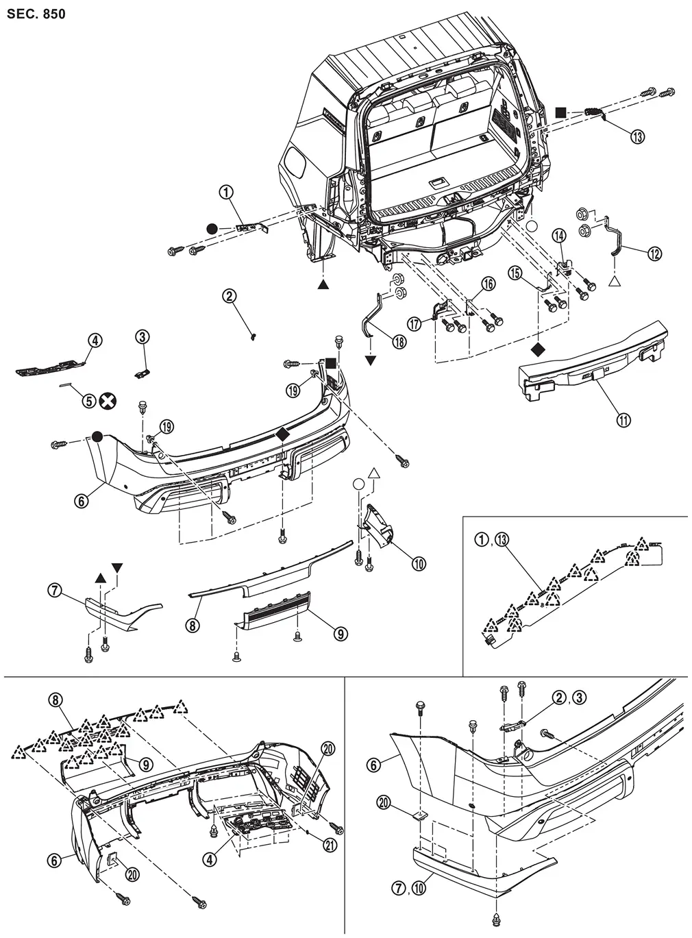
 |
Rear bumper side bracket LH |  |
Rear bumper bracket RH |  |
Rear bumper bracket LH |
 |
Hands free sensor bracket (with hands free sensor models) |
 |
Double-sided tape [t: 1.2 mm (0.047 in)] (with hands free sensor models) |
 |
Rear bumper fascia |
 |
Rear bumper molding LH |  |
Rear bumper finisher upper |  |
Rear bumper finisher lower |
 |
Rear bumper molding RH |  |
Rear bumper energy absorber |  |
Rear bumper side stay RH |
 |
Rear bumper side bracket RH |  |
Rear bumper stay A RH |  |
Rear bumper stay B RH |
 |
Rear bumper stay B LH |  |
Rear bumper stay A LH |  |
Rear bumper side stay LH |
 |
Grommet |  |
U nut |  |
Bumper clip (with hands free sensor models) |
 |
: Pawl | ||||
 |
: Always replace after every disassembly. | ||||
 , , , ,  , ,  , ,  , ,  , ,  : Indicates that the part is connected at points with same symbol in actual vehicle. : Indicates that the part is connected at points with same symbol in actual vehicle. |
|||||
Removal and Installation
WARNING:
CAUTION:
Rear bumper fascia assembly is made of resin. Never apply excessive force to it, and be careful to prevent contact with oil.
REMOVAL
Remove rear combination lamp. Refer to Removal and Installation.
Remove fixing clips  and screws
  .
.
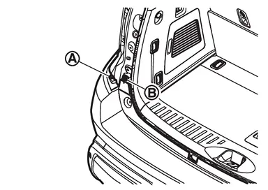
Remove mounting bolts .
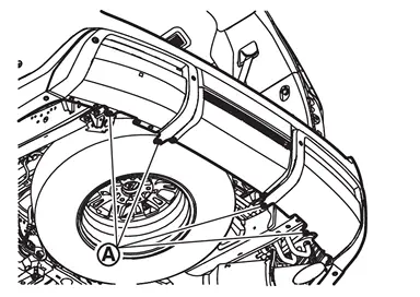
Remove fixing screws and mounting bolts .
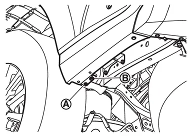
Remove fixing screws .
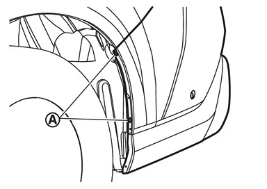
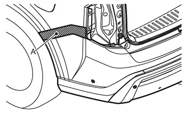
Apply protective tapes (A) on the part to protect it from damage.
Pull rear bumper fascia side toward the vehicle side to disengage the fitting of rear bumper side bracket and rear bumper fascia side according to the numerical order 1→2 as shown by the arrows in the figure.
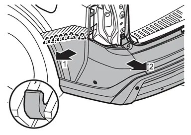
|
: Pawl |
CAUTION:
When disenagage rear bumper fascia assembly, 2 workers are required so as to prevent it from dropping.
Disconnect rear sonar sensor harness connector.
Disconnect rear side radar harness connector.
Remove rear bumper fascia assembly.
CAUTION:
When removing rear bumper fascia assembly, 2 workers are required so as to prevent it from dropping.
Remove the following parts after removing rear bumper fascia assembly.
-
Rear sonar sensor. Refer to SONAR SENSOR (REAR) : Removal & Installation.
-
Rear side radar. Refer to Removal and Installation.
-
Rear reflex reflector. Refer to Removal and Installation.
-
Hands free control unit and hands free sensors. Refer to Removal and Installation.
-
Bumper clips
-
Hands free sensor bracket
-
Rear bumper molding (LH and RH)
-
U nuts
-
Rear bumper bracket (LH and RH)
-
Grommets
-
Rear bumper finisher upper
-
Rear bumper finisher lower
Remove rear bumper energy absorber.
Remove mounting bolts, and then remove rear bumper stay A (LH and RH).
Remove mounting bolts, and then remove rear bumper stay B (LH and RH).
Remove mounting nuts, and then remove rear bumper side stay (LH and RH).
Remove rear bumper side bracket (LH and RH) fixing screws.
Disengage fixing pawls, and then remove rear bumper side bracket (LH and RH).
INSTALLATION
Note the following items, and then install in the reverse order of removal.
CAUTION:
-
Perform side radar alignment. Refer to Work Procedure.
-
Always replace double-sided tape with a new one when installing hands free sensor bracket.
-
Degrease a double-sided tape mounting surface.
-
Never wash the vehicle within 24 hours after installing so as to keep adhesive.
 NOTE:
NOTE:
-
After installing rear bumper finisher to rear bumper fascia, install rear bumper fascia assembly to the vehicle body.
-
If it is difficult to install the clips when assembling rear bumper finisher, install them in the following order.
-
Disassembly clips into pin and grommet.
-
Install grommet to rear bumper finisher.
-
Install pin into grommet.
-
-
The following table shows the specified values for checking normal installation status.
-
Fitting adjustment cannot be performed.
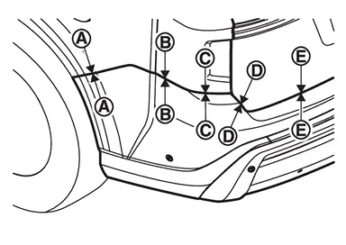
Portion Clearance Surface height difference Rear bumper fascia assembly – Body side outer panel – 0.1 - 1.0 mm
(0.004 - 0.039 in)(-1.5) - (+1.5) mm
[(-0.059) - (+0.059) mm]Rear bumper fascia assembly – Rear combination lamp – 0.1 - 2.9 mm
(0.004 - 0.114 in)(-1.2) - (+1.6) mm
[(-0.047) - (+0.063) mm] –
– 0.1 - 2.9 mm
(0.004 - 0.115 in)(-1.0) - (+1.4) mm
[(-0.039) - (+0.055) mm]Rear bumper fascia assembly – Back door assembly  –
– 3.0 - 7.0 mm
(0.118 - 0.276 in)(-1.0) - (+3.0) mm
[(-0.039) - (+0.118) mm] –
– 4.0 - 8.0 mm
(0.157 - 0.315 in)(-1.3) - (+2.7) mm
[(-0.051) - (+0.106) mm]
Inspection
SIDE RADAR IRRADIATION AREA
-
For side radar irradiation area, refer to the figure below.
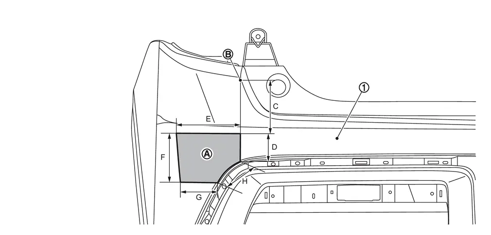
Rear bumper fascia Side radar irradiation area Reference point (R end) C 115 mm
(4.53 in) (vertical line)D 70 mm
(2.76 in) (vertical line)E 215 mm
(8.46 in) (horizontal line)F 105 mm
(4.13 in) (vertical line)G 150 mm
(5.91 in) (horizontal line)H 70 mm
(2.76 in) (reference dimension) -
The dimensions are along the bumper fascia surface between each reference point.
-
Repairs in the side radar irradiation area may affect side radar performance. Carefully check the dimensions noted under the diagram.
REPAIR AND MENDING OF IRRADIATION AREA OF SIDE RADAR
CAUTION:
For repair and mending of irradiation area of side radar, be careful with the following.
-
Do not leave cracks, scratches and deformations in the side radar irradiation area.
-
Side radar performance may be affected by the repair of irradiation area of bumper. Carefully follow these instructions when repairing the bumper of a vehicle equipped with side radars.
Only one layer of color base coat may be applied and recoating is not allowed.
Use only body exterior paint colors approved for this model.
After applying color base paint inside the radar irradiation area, perform side radar alignment, even if bumper is not removed/reinstalled. Refer to Work Procedure. Clear painting Allowed (with conditions)Clear paint must be applied uniformly with only one layer inside the irradiation area. (No clear paint fading-out or recoating inside the area is allowed.)
After applying clear paint inside the radar irradiation area, perform side radar alignment, even if bumper is not removed/reinstalled. Refer to Work Procedure. 5 Removal of dust from surface to be painted by polishing, buffing, and base treatment before coating. Allowed -
For details of each instruction, refer to followings.
-
Installation of sticker, accessories, aluminum tape and wrapping film, etc.
Do not install sticker, accessories, aluminum tape and wrapping tape, etc. to side radar irradiation area. (Including transparent one)
-
Coating and wax, etc.
-
It is possible to apply coating and wax to side radar irradiation area.
-
Surface treatment at the start of the work can be applied.
-
-
Repair of cuts, holes, cracks, scratches and deformations.
The repair inside radar irradiation area is prohibited. Be sure to perform new rear bumper replacement. Refer to Removal and Installation.
Cannot be repaired
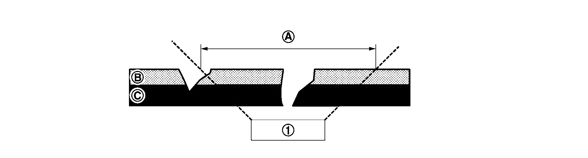
Side radar Irradiation area Existing paint film Bumper fascia plastic -
Paint repair
Putty application: Prohibited
-
Radar irradiation area cannot be repaired by applying putty. (Both partial applications are prohibited)
Color base painting: Allowed (with conditions)
NOTE:
To minimize the influence on side radar performance which may cause by color base painting, follow the instructions below:
-
To remove all existing paint films inside radar irradiation area by using #800 sandpaper.
-
If removing existing paint films causes scratches on the surface, perform replacement with a new bumper.
-
Color base (including plastic primer and primer surfacer) painting can be performed only once inside radar irradiation area and recoating is not allowed. (Definition of once is until the color base coat is dyed, not the times of sprays.)
-
When applying primer tinted sealer, etc., use the product which is recommended by paint supplier to improve the hiding of color base and reduce color base coat thickness.
-
When spray mist may stick on the reverse side of the bumper fascia, conduct to perform masking on the reverse side of the bumper to prevent spray mist adhesion.
-
Only the body exterior colors adopted for this model can be painted.
-
To use the paint suppliers, products which are approved by Nissan. Please contact each paint supplier accordingly for more information.
-
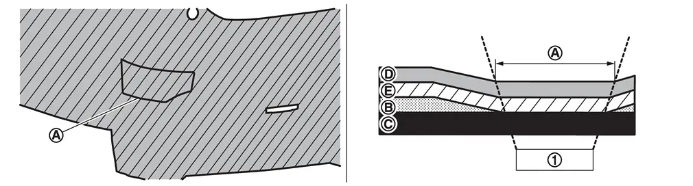
Step 1 : Before repair
Can be performed
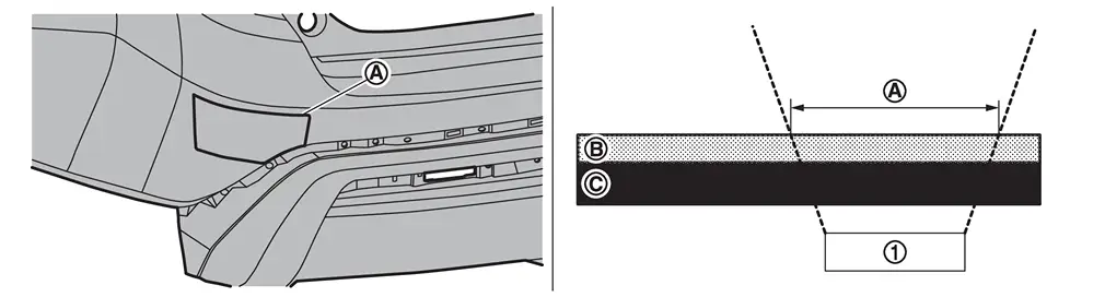
Side radar Irradiation area Existing paint film Bumper fascia plastic -
Step 2 : After removing existing paint film
Can be performed
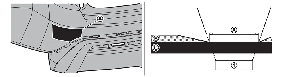
Side radar Irradiation area Existing paint film Bumper fascia plastic -
Step 3 : After color base and clear painting are performed.
Can be performed
Side radar Irradiation area Existing paint film Bumper fascia plastic Clear paint film Color base paint film
Conditions that color base painting cannot be performed:
-
Painting on existing paint films inside irradiation area is not allowed. (Both block painting and fade-out painting are prohibited.)
Cannot be performed
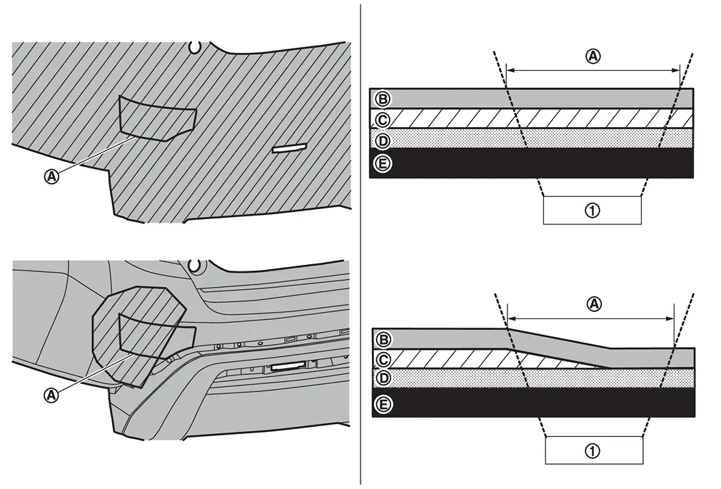
Side radar Irradiation area Clear paint film Color base paint film Existing paint film *1 Bumper fascia plastic *1 : Painting on remaining paint films is not allowed.
-
Color base recoating is not allowed.
Cannot be performed
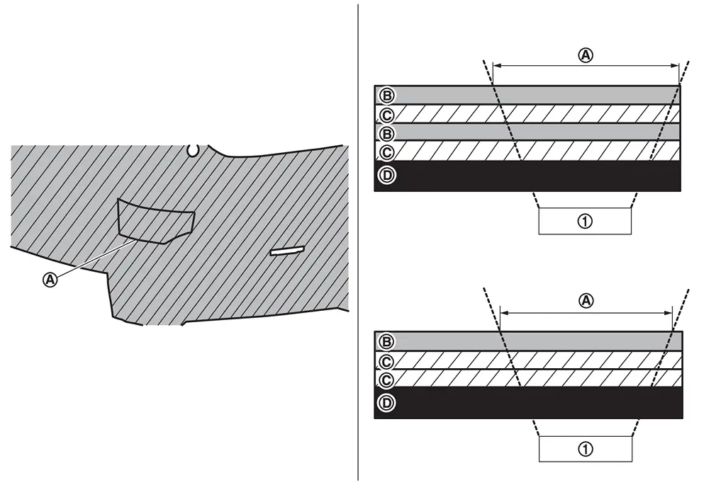
Side radar Irradiation area Clear paint film Color base paint film Bumper fascia plastic
Clear painting: Allowed (with conditions)
-
Clear painting can be performed only once inside radar irradiation area, on existing new vehicle paint films (including newly painted bumper for replacement). Definition of once is until the color coat is formed, not the times of sprays.
-
Conditions that clear painting can be performed:
-
When color base painting area (plastic primer, putty, primer surfacer, pearl base, color clear base and under clear, etc.) does not cover the irradiation area and clear painting is uniformly performed.
Can be performed
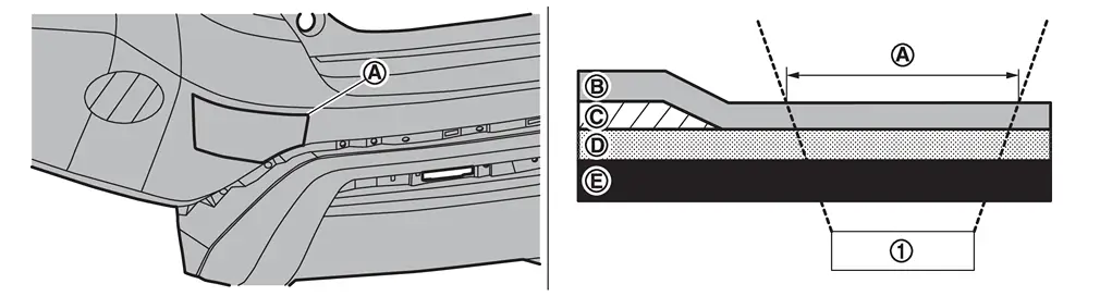
Side radar Irradiation area Clear paint film Color base paint film Existing new vehicle paint films Bumper fascia plastic -
When clear painting is uniformly performed inside the irradiation area. (The whole part is painted.)
Can be performed
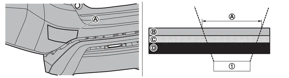
Side radar Irradiation area Clear paint film Existing new vehicle paint films Bumper fascia plastic
Conditions that clear painting cannot be performed:
-
When clear painting is not uniformly performed inside the irradiation area. (Clear paint fade-out is prohibited.)
Cannot be performed
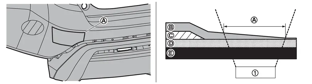
Side radar Irradiation area Clear paint film Color base paint film Existing new vehicle paint films Bumper fascia plastic -
When clear paint recoating is performed inside the irradiation area.
Cannot be performed
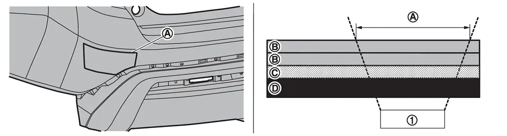
Side radar Irradiation area Clear paint film Existing new vehicle paint films Bumper fascia plastic
-
-
Polishing on paint surface
Polishing is allowed (including removing dust on the paint surface, gloss improvement, base treatment before coating, etc.).
Other materials
Additional Service When Replacing Transfer Control Unit
Description
When replacing transfer control unit, the following work is required. For the work procedure, refer to Work Procedure.WORK AFTER REPLACEMENT
Unit parameter writing
Initial calibration
Work Procedure
WRITING THE REQUIRED INFORMATION FOR CONTROL UNIT REPLACEMENT
With CONSULT
Ignitio ...
Front Propeller Shaft
Exploded View
REMOVAL
Propeller shaft assembly
: vehicle front
: N·m (kg-m, ft-lb)
: Always replace after every disassembly.
DISASSEMBLY
Snap ring
Journal bearing
Journal
Flange yoke
Propeller shaft tube
: Select with proper thickness. ...
Parameter Writing
Work Procedure
DescriptionWhen replace each camera, it is necessary to write the camera parameters using CONSULT.Write to around view monitor control unit according to "Parameter writing" procedure of "CONSULT Operation Manual".Work ProcedurePARAMETER WRITING
CONSULT
Ignition switch ON.
Select " ...