
Nissan Armada 2025-2026 Service and Repair Manual: Inspection
INSPECTION PROCERDURE
Trouble Diagnosis of Turbocharger
Check items before trouble diagnosis
Check that the engine oil level is between L (Low level) and H (High level) of the oil level gauge. [When the engine oil amount is more then H (High level), the engine oil flows into the inlet duct through the blow-by gas passage, and the turbocharger is misjudged failure.]
Ask the customer if he/she always runs the vehicle in idle engine speed to cool the engine oil down after driving.
Replace the turbocharger assembly when any malfunction is found after unit inspections specified in the table below.
If no malfunction is found after the unit inspections, judge that the turbocharger body has no non-standard conditions. Check the other parts again.
Inspection Location Result Symptoms likely to occur when the results shown on the left exist. Oil leakage Smoke Noise* Poor power
Poor accelerationTurbine wheel Wet with oil. C A C C Carbon deposits observed. C A B B “Rubs against� housing. C B A B Vane is bent or broken. A A Compressor wheel Inside of intake port is badly stained with oil. B B “Rubs against� housing. C B A B Vane is bent or broken. A A Check both turbine and compressor rotor shaft end play. Heavy feel or catching when turned by hand. C C B Cannot be turned by hand. A Excessively loose bearing. C C B C Rotor shaft, oil return port (Check inside using penlight.) Carbon or sludge deposits in oil drain port. B A C C Boost control valve actuator operation (using a handy pump) Does not operate smoothly when air pressure is gradually applied.
Stroke amount is not compliance with the air pressure.
A A: Highly possible. B: Possible. C: May exist. * Racing under cold engine may generate a noise from the area of wastegate valve. This is not a turbocharger malfunction. The noise stops after engine warm-up.
INSPECTION AFTER REMOVAL
Bank1 side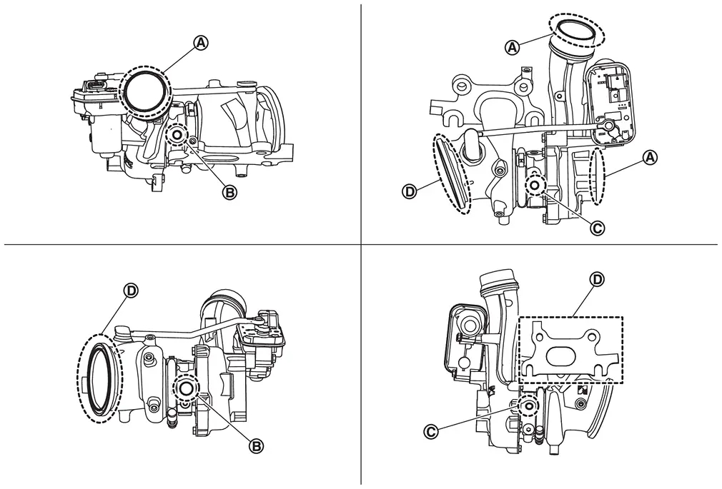
 | Location to check for air leaks |  | Location to check for engine oil leaks |  | Location to check for engine coolant leaks |
 | Location to check for exhaust gas leaks |
Bank2 side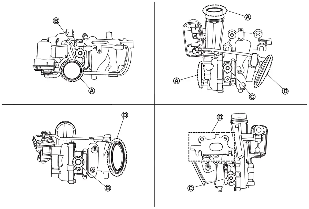
| Location to check for air leaks | | Location to check for engine oil leaks | | Location to check for engine coolant leaks |
| Location to check for exhaust gas leaks |
CAUTION:
When the compressor wheel, turbine wheel or rotor shaft is damaged, remove all the fragments and foreign matter left in the following passages in order to prevent a secondary failure:
| Intake side | : Between turbocharger and charge air cooler |
| Exhaust side | : Between turbocharger and outlet duct |
INSPECTION AFTER INSTALLATION
Start engine and raise engine speed to check no exhaust emission leaks.
 Removal & Installation
WARNING:
REMOVAL
Disconnect battery cables from negative terminal. Refer to Exploded View.
Drain engine coolant. Refer to ENGINE COOLANT : Draining.
CAUTION:
Perform this step when the engine is cold ...
 Vtc
Vtc
...
Other materials:
Diagnosis Procedure
PERFORM SELF-DIAGNOSIS OF DISPLAY UNIT
Perform “Self Diagnostic Result� of “Display unit�.
Is DTC detected?
YES>>
Perform diagnosis procedure on the detected DTC. Refer to DTC Index.
NO>>
GO TO 2.
PERFORM SELF-DIAGNOSIS OF COMBINATION METER
Perform “Self Diagnostic Result� ...
Exploded View
High-mounted stop lamp harness Rear spoiler High-mounted stop lamp : Pawl : N·m (kg-m, in-lb) ...
Diagnosis Procedure
CHECK POWER SOURCE AND GROUND CIRCUIT
Turn ignition switch OFF.
Remove the heated steering wheel. Refer to Removal and Installation.
Turn ignition switch ON.
CAUTION:
Never start the engine.
Turn heated steering wheel switch ON.
Check voltage between spiral cable harness connector terminals.
Spiral ...

0.0051