
Nissan Armada 2025-2026 Service and Repair Manual: Removal & Installation
WARNING:
REMOVAL
Disconnect battery cables from negative terminal. Refer to Exploded View.
Drain engine coolant. Refer to ENGINE COOLANT : Draining.
CAUTION:
Perform this step when the engine is cold.
Never spill engine coolant on drive belt.
Remove the following parts:
Drive belt. Refer to Removal & Installation
Air cleaner and air duct assembly. Refer to Removal and Installation.
Inlet air duct 2. Refer to Removal and Installation.
Air inlet tube 1 and 2. Refer to Removal & Installation.
Intake manifold. Refer to Removal and Installation
Main muffler. Refer to EXHAUST SYSTEM : Removal & Installation.
Bank 1 side
Remove front tire assembly (RH). Refer to ROAD WHEEL TIRE : Removal & Installation.
Remove fender protector (RH). Refer to Removal and Installation.
Remove 2nd catalyst converter (bank 1). Refer to Removal and Installation.
Remove heat insulator (upper)  .
.
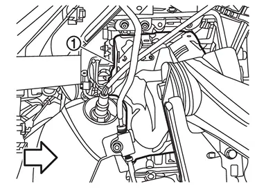
 | : Engine front |
Remove catalyst converter (bank 1). Refer to Removal and Installation.
Remove starter motor. Refer to Removal and Installation.
Remove alternator. Refer to Removal and Installation.
Remove oil return pipe 1 from the turbocharger assembly  side.
side.
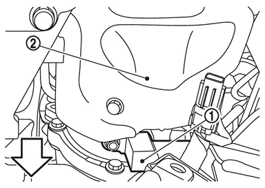
| : Engine front |
Remove air duct 3. Refer to Removal and Installation.
Remove water hose 1. Refer to Removal and Installation
Remove mounting bolt  of water outlet tube .
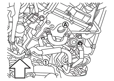
| : Engine upper |
Remove water inlet tube .
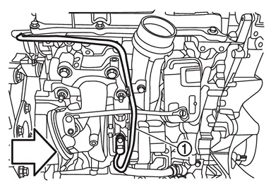
| : Engine front |
Remove mounting bolt of oil feed tube .
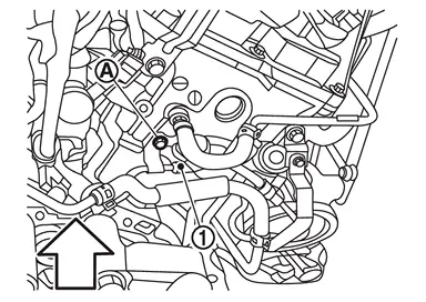
| : Engine upper |
Remove each hose connected to water pipe 1. Refer to Removal and Installation.
Remove water pipe 1. Refer to Removal and Installation.
Remove front heater pipe assembly. Refer to Exploded View.
Remove oil feed tube from the oil inlet adapter side.
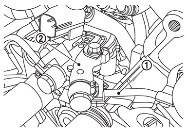
CAUTION:
Do not reuse eye bolt gaskets.
Disconnect turbocharger speed sensor harness connector.
Loosen turbocharger assembly mounting nuts in the order from 4 to 1 as shown in the figure.
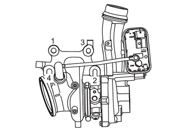
Move the turbocharger assembly to the rear of the engine. Remove turbocharger assembly from the top of the engine by rotating it vertically in the following order.
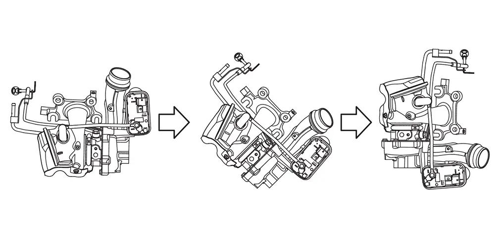
CAUTION:
Be careful not to bend the oil feed tube and water outlet tube.
Remove gasket 1.
CAUTION:
Do not reuse turbocharger gasket.
Bank 2 side
Remove front tire assembly (LH). Refer to ROAD WHEEL TIRE : Removal & Installation.
Remove fender protector (LH). Refer to Removal and Installation.
Release fuel pressure. Refer to Work Procedure.
Discharge refrigerant from A/C circuit. Refer to Recycle Refrigerant.
Remove 2nd catalyst converter. Refer to Removal and Installation.
Remove heat insulator (upper) .
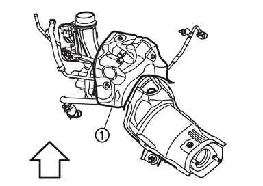
| : Engine upper |
Remove catalyst converter (bank 2). Refer to Removal and Installation.
Remove A/C compressor belt. Refer to Removal & Installation.
Remove EVAP canister purge volume control solenoid valve and the connected hose as a set. Refer to Exploded View.
Remove fuel feed hose. Refer to Removal & Installation.
Remove ground cable. Refer to Exploded View.
Remove each hose connected to water pipe 2. Refer to Removal and Installation.
Remove water pipe 2. Refer to Removal and Installation.
Remove high pressure flexible hose and low pressure flexible hose. Refer to Exploded View.
Remove A/C compressor. Refer to Removal and Installation.
Remove air duct 3. Refer to Removal and Installation.
Remove oil level gauge and oil level gauge guide. Refer to Exploded View.
Disconnect the sub harness connector. Refer to Exploded View.
Remove oil feed tube from the inlet adapter side.
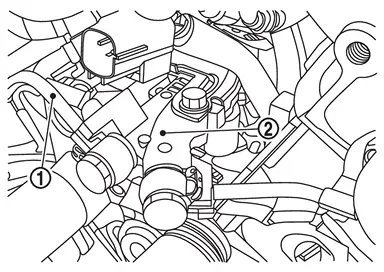
CAUTION:
Do not reuse eye bolt gaskets.
Remove mounting bolt of oil feed tube .
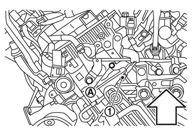
| : Engine upper |
Disconnect turbocharger speed sensor harness connector.
Loosen turbocharger assembly mounting nuts in the order from 4 to 1 as shown in the figure.
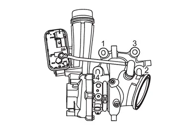
Remove turbocharger assembly.
CAUTION:
Be careful not to bend the oil feed tube and water outlet tube.
Remove gasket 2.
CAUTION:
Do not reuse turbocharger gasket.
Oil feed tube
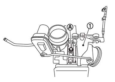
Fix the turbocharger in a vise (A).
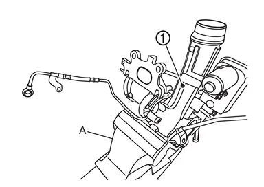
Remove oil feed tube mounting bolts from the turbocharger .
INSTALLATION
 NOTE:
NOTE:
If a turbocharger assembly is replaced, carry out the reset of adaption of “Turbocharger Wastegate Control Solenoid Valve Data Initialization�. Refer to Work Procedure.
Turbocharger side
Install in the reverse order of removal.
Install turbocharger assembly in the reverse order of removal and in the order shown in the figure. (Bank 1 side).
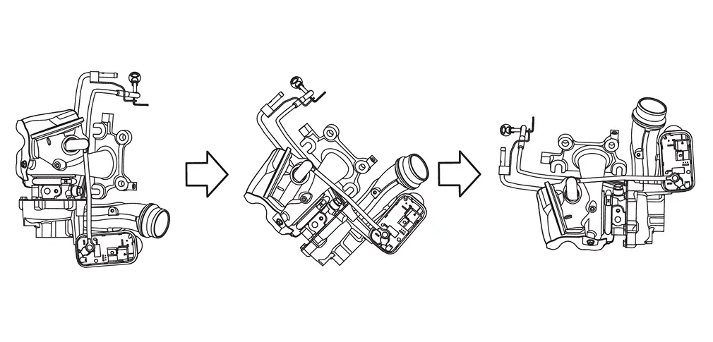
CAUTION:
Be careful not to bend the oil feed tube and water outlet tube.
Install turbocharger assembly in the order from 1 to 4 as shown in the figure.
 | : 34.5 N·m (3.5 kg-m, 25 ft-lb) |
Install oil return pipe.
Install water tube according to the following procedure.
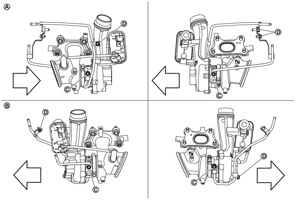
| : Bank 1 |
 | : Bank 2 |
| : Engine front |
 . Temporarily tighten bracket bolt
  . Tighten water tube bolt to the torque specified below.
 | : 9.0 N·m (0.92 kg-m, 80 in-lb) |
Install water hose.
Align with paint mark (Yellow).
Install the oil feed tube with the following procedure.
| : Bank 1 |
| : Bank 2 |
| : Engine front |
Temporarily tighten eye bolt.
Tighten eye bolt to the torque specified below.
: 17.0 N·m (1.7 kg-m, 13 ft-lb) CAUTION:
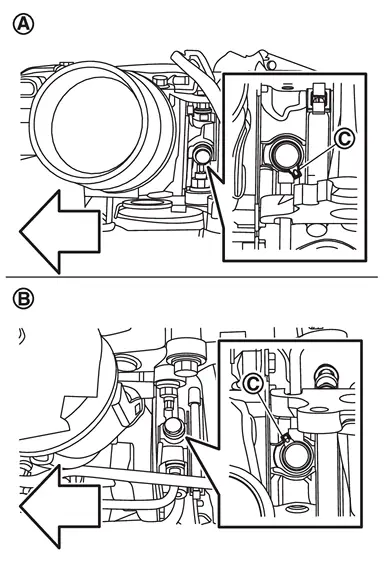
Position gasket protrusion
as shown in the figure.
Oil inlet adapter
Install oil inlet adapter.
Temporarily tighten eye bolt .
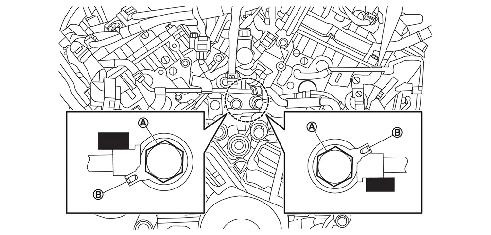
CAUTION:
Position gasket protrusion as shown in the figure.
Temporarily tighten mounting bolt of oil feed tube . (Bank 1 side)
| : Vehicle front |
Temporarily tighten mounting bolt of oil feed tube . (Bank 2 side)
| : Vehicle front |
Tighten to the specified torque eye bolt .
| : 25.0 N·m (2.6 kg-m, 18 ft-lb) |
CAUTION:
Position gasket protrusion as shown in the figure.
Tighten to the specified torque mounting bolt of oil feed tube . (Bank 1 side).
| : Vehicle front |
| : 9.0 N·m (0.92 kg-m, 80 in-lb) |
Tighten to the specified torque mounting bolt of oil feed tube . (Bank 2 side).
| : Vehicle front |
| : 9.0 N·m (0.92 kg-m, 80 in-lb) |
 Exploded View
Bank 1 side
Water inlet hose Clamp Water inlet tube O-ring Heat insulator (upper) Oil return pipe 1 Oil return hose Oil return pipe 2 Heat insulator (lower) Water outlet tube Turbocharger ...
 Inspection
INSPECTION PROCERDURE
Trouble Diagnosis of Turbocharger
Check items before trouble diagnosis
Check that the engine oil level is between L (Low level) and H (High level) of the oil level gauge. [When t ...
Other materials:
Sanding
Aluminum alloy panels are softer than steel plates. It is important to select the proper type and grade of sanding disc. Also, care must be taken not to overgrind the surface.
Because aluminum powder is light and tends to float in the air, eyes and respiratory parts of the body must be fully protect ...
Inspection
AFTER A COLLISION
WARNING:
To avoid the risk of death or severe injury:
Replace any seat belt assembly (including anchor bolts) if:
Anchor bolts are deformed or worn out.
PRELIMINARY CHECKS
Check the shoulder seat belt guide for second seat. Check that guide swivels freely and that webbing lays fla ...
Tire labeling
Example
Basic information
In the Nissan Armada, all tires are required by federal regulations to display
standardized information directly on the sidewall.
This labeling provides essential data about the tire’s construction, performance
capabilities, and specifications, allowing Nissan ...

0.0057