
Nissan Armada 2025-2026 Service and Repair Manual: Inspection and Adjustment
INSPECTION
Brake Pedal Height
Check the height (H1) between the floor panel  and the brake pedal upper surface.
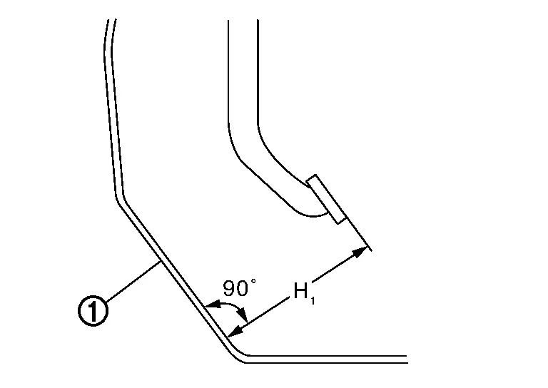
| H1 | : Refer to Brake Pedal. |
CAUTION:
Remove the front floor carpet.
Stop Lamp Switch
Check the clearance (A) among the brake pedal lever  and the stop lamp switch mounting bracket
  .
.
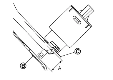
| A | : Refer to Brake Pedal. |
CAUTION:
The stop lamp must turn off when the brake pedal is released.
 NOTE:
NOTE:
Never touch the brake pedal (pad) when checking the clearance between brake pedal lever and stop lamp switch.
Brake Pedal Play
Press the brake pedal. Check the brake pedal play (A) (stroke until fluid pressure occurs).
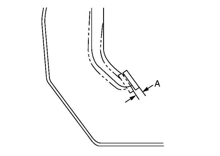
| A | : Refer to Brake Pedal. |
Depressed Brake Pedal Height
Check the height between the floor panel and the brake pedal upper surface (H2) when depressing the brake pedal at 490 N (50 kg, 110 lb) while engine ON.
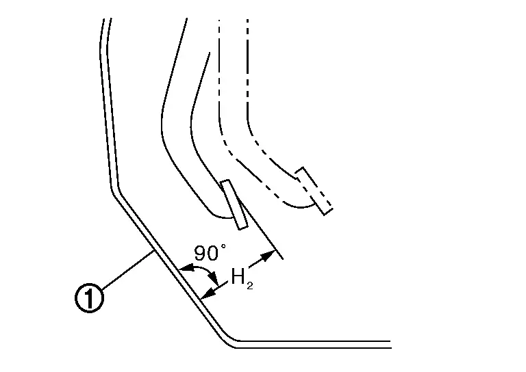
| H2 | : Refer to Brake Pedal. |
CAUTION:
Remove the front floor carpet.
ADJUSTMENT
Brake Pedal Height
Perform the following procedure when brake pedal height is not within the specified value because brake pedal height is not adjustable.
Replace brake pedal assembly when input rod length is within specified value. Refer to Inspection.
Stop Lamp Switch
Remove instrument lower panel LH. Refer to Removal and Installation.
Disconnect the harness connector from stop lamp switch.
Loosen the stop lamp switch 90 degree counterclockwise.
Install stop lamp switch , follow the procedure below.
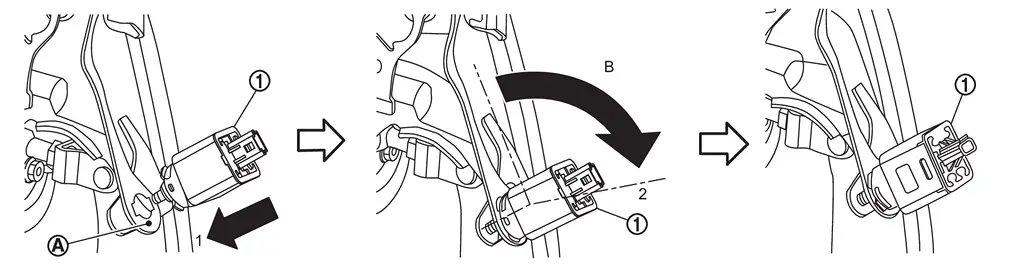
 .
.
| B | : About 90 degree |
CAUTION:
The clearance (A) between the brake pedal lever
and stop lamp switch mounting bracket must be the specified value.A : Refer to Brake Pedal. The stop lamp must be turned off when the brake pedal is released.
Depressed Brake Pedal Height
Perform the air bleeding. Refer to Work Procedure.
Check the height between the floor panel and the brake pedal upper surface (H2) when depressing the brake pedal at 490 N (50 kg, 110 lb) while engine ON.
| H2 | : Refer to Brake Pedal. |
CAUTION:
Remove the front floor carpet.
 Brake Pedal
...
 Brake Fluid
...
Other materials:
Precaution for Chassis Control
Never disassemble the chassis control module.
The parts must not be reused if they are dropped.
Never perform "Active Test" while driving the vehicle.
When the intelligent trace control function is activated, the driver may feel some vibration on the brake pedal, hear operating sounds, or feel the d ...
Exploded View
Washer tank assembly Packing Hoodledge assembly RH Washer tank inlet Washer tank cap : N·m (kg-m, in-lb) ...
Disassembly and Assembly
DISASSEMBLY
Remove the following parts:
Oil pan (lower): Refer to Removal and Installation.
Oil pan (upper): Refer to Disassembly and Assembly.
Timing chain: Refer to Removal and Installation.
Cylinder head: Refer to Removal & Installation.
Oil strainer and oil pump: Refer to Removal and Insta ...

0.0053