
Nissan Armada 2025-2026 Service and Repair Manual: Disassembly and Assembly
DISASSEMBLY
Remove the following parts:
Oil pan (lower): Refer to Removal and Installation.
Oil pan (upper): Refer to Disassembly and Assembly.
Timing chain: Refer to Removal and Installation.
Cylinder head: Refer to Removal & Installation.
Oil strainer and oil pump: Refer to Removal and Installation.
Baffle plate
Remove knock sensor.
CAUTION:
Carefully handle sensor avoiding shocks.
Remove piston and connecting rod assembly with the following procedure:
Before removing piston and connecting rod assembly, check the connecting rod side clearance. Refer to Inspection.
CAUTION:
Never drop connecting rod bearing, and to scratch the surface.
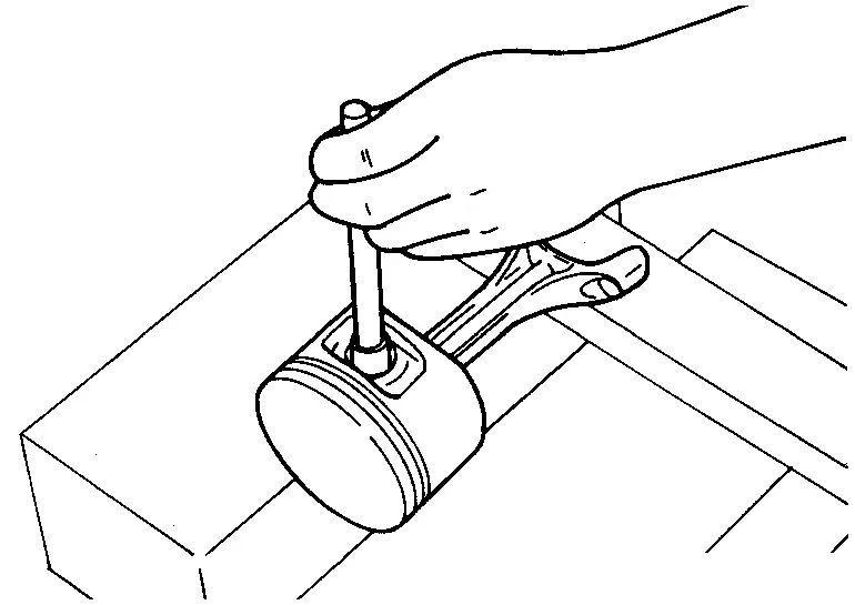
Position crankshaft pin corresponding to connecting rod to be removed onto the bottom dead center. Remove connecting rod bearing cap. Using a hammer handle or similar tool, push piston and connecting rod assembly out to the cylinder head side.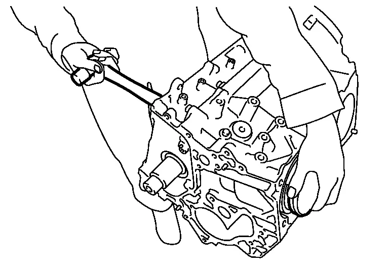
CAUTION:
Never damage the cylinder wall and crankshaft pin, resulting from an interference of the connecting rod big end.
Remove connecting rod bearings from connecting rod and connecting rod bearing cap.
CAUTION:
Never drop connecting rod bearing, and to scratch the surface.
Identify installation positions, and store them without mixing them up.
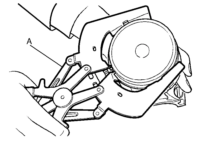
Remove piston rings from piston.
Before removing piston rings, check the piston ring side clearance. Refer to Inspection.
Use a piston ring expander (commercial service tool) (A).
CAUTION:
When removing piston rings, be careful not to damage piston.
Never damage piston rings by expanding them excessively.
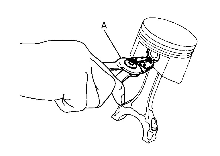
Remove piston from connecting rod as follows: Using snap ring pliers (A), remove snap rings.
Remove lower cylinder block bolts.
Before loosening lower cylinder block bolts, measure the crankshaft end play. Refer to Inspection.
Loosen lower cylinder block bolts in the order from 26 to 1 shown in the figure in several different steps.
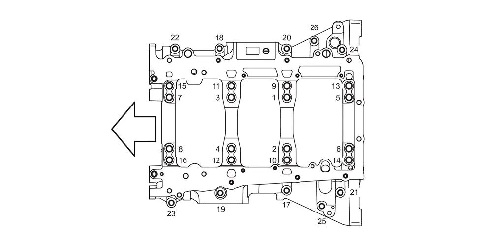

: Engine front
Remove lower cylinder block as follows:
Screw M8 bolt [pitch: 1.25 mm (0.049 in) length: approximately 50 mm (1.97 in)] into bolt holes  . Then equally tighten each bolt, and remove lower cylinder block.
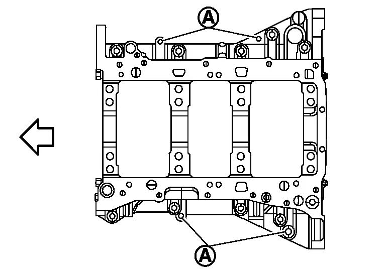
| : Engine front |
CAUTION:
Never damage the mounting surfaces.
Never tighten bolts excessively.
Never insert screwdriver, this will damage the mating surface.
Remove crankshaft.
Pull rear oil seal out from rear end of crankshaft.
Remove main bearings and thrust bearings from cylinder block and lower cylinder block.
CAUTION:
Never drop main bearing, and to scratch the surface.
Identify installation positions, and store them without mixing them up.
Remove oil jet.
ASSEMBLY
CAUTION:
Do not reuse O-rings or washers.
 NOTE:
NOTE:
If a piston, connecting rod or crankshaft are removed, carry out teach of “Electric IVT Control Actuator Position Learning�. Refer to Work Procedure.
Fully air-blow engine coolant and engine oil passages in cylinder block, cylinder bore and crankcase to remove any foreign material.
CAUTION:
Use goggles to protect your eyes.
Install each plug to cylinder block as shown in the figure.
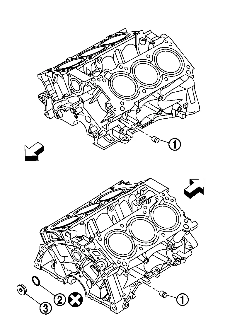
 | : Plug |
| : Engine front |
Apply sealant to the thread of water drain plug
 .
.CAUTION:
Do not reuse washers.
Apply sealant to the thread of plug.
Use Genuine High Strength Locking Sealant or an equivalent. Refer to Recommended Chemical Products and Sealants.
Replace washer
 with new one.
Tighten each plug as specified below.
Unit: N·m (kg-m, ft-lb)
Part Washer Tightening torque No 19.6 (2.0, 14) Yes 78.0 (8.0, 58)
Install oil jet.
Install main bearings and thrust bearings as follows:
CAUTION:
Never drop main bearing, and to scratch the surface.
Remove dust, dirt, and engine oil on bearing mating surfaces of cylinder block and lower cylinder block. Install thrust bearings to both sides of the No. 3 journal housing on cylinder block.
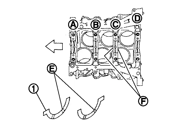
| : No. 1 |
 | : No. 2 |
 | : No. 3 |
 | : No. 4 |
 | : Thrust bearing installation position |
| : Engine front |
Install thrust bearings with the oil groove
 facing crankshaft arm (outside).
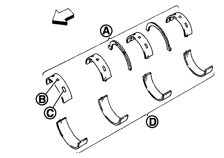
| : Cylinder block side |
| : Lower cylinder block side |
| : Engine front |
Main bearing with oil hole
and groove goes on cylinder block. The one without them goes on lower cylinder block.Before installing main bearings, apply engine oil to the bearing surface (inside). Do not apply engine oil to the back surface, but thoroughly clean it.
When installing, align main bearing stopper protrusion to cutout of cylinder block and lower cylinder block.
Ensure the oil holes on cylinder block and those on the corresponding bearing are aligned.
Install crankshaft to cylinder block.
While turning crankshaft by hand, check that it turns smoothly.
Install lower cylinder block.
CAUTION:
Do not reuse O-rings.
NOTE:
Lower cylinder block cannot be replaced as a single part, because it is machined together with cylinder block.
Apply a continuous bead of liquid gasket
with the tube presser (commercial service tool) to lower cylinder block as shown in the figure.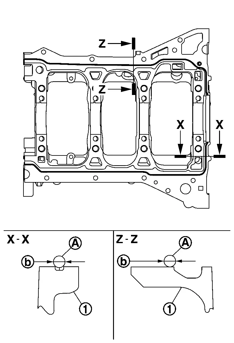

: φ3.4 - 4.4 mm (0.134 - 0.173 in)
Inspect the outer diameter of lower cylinder block bolt. Refer to Inspection.
Install lower cylinder block bolts in numerical order as shown in the figure as follows:Apply new engine oil to threads and seat surfaces of lower cylinder block bolts. Tighten bolts (No. 17 to 26) in numerical order as shown in the figure.
| : Engine front |
 : 25.1 N·m (2.6 kg-m, 19 ft-lb) : 25.1 N·m (2.6 kg-m, 19 ft-lb) |
CAUTION:
Do not reuse O-rings.
Repeat step b. Tighten bolts (No. 1 to 16) in numerical order as shown in the figure.
| : Engine front |
NOTE:
Use TORX socket (commercial service tool) for bolts No.1 to 16.
| : 44.2 N·m (4.5 kg-m, 33 ft-lb) |
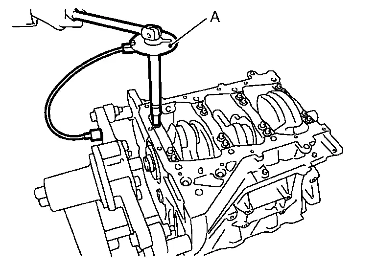
CAUTION:
Use the angle wrench [SST: KV10112100 (BT-8653-A)] (A) to check tightening angle. Never make judgment by visual inspection.
After installing lower cylinder block bolts, check that crankshaft can be rotated smoothly by hand.
Check the crankshaft end play. Refer to Inspection.
Install piston to connecting rod as follows: Using snap ring pliers, install new snap ring to the groove of piston rear side.
Insert it fully into groove to install.
Using an industrial use dryer or similar tool, heat piston until piston pin can be pushed in by hand without excess force [approximately 60 to 70°C (140 to 158°F)]. From the front to the rear, insert piston pin into piston and connecting rod.
Assemble so that the front mark on the piston head and the cylinder number on connecting rod are positioned as shown in the figure.
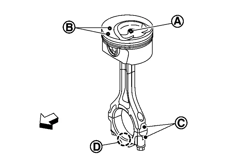
: Two dimensional code : Front mark : Cylinder number : Front mark : Engine front
Insert it fully into groove to install.
After installing, check that connecting rod moves smoothly.
Using a piston ring expander (commercial service tool) (A), install piston rings.
CAUTION:
When installing piston rings, be careful not to damage piston.
Never damage piston rings by expending them excessively.
If there is stamped mark on ring, mount it with marked side up.
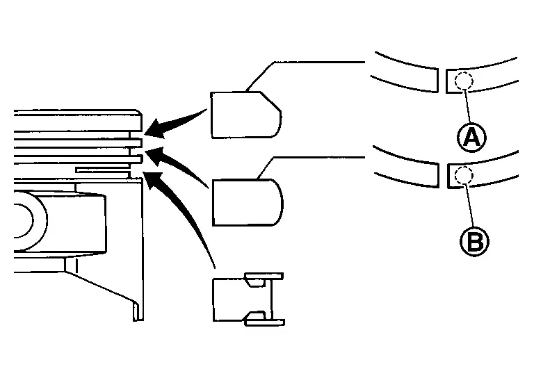
Stamped mark: Top ring : 1 N Second ring : 2 N Position each ring with the gap as shown in the figure referring to the piston front mark
.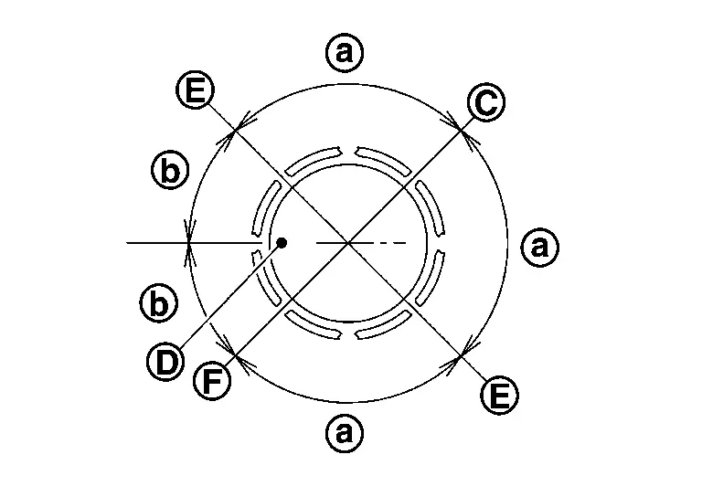
: Top ring gap : Oil ring upper or lower rail gap (either of them) : Second ring and oil ring spacer gap 
: 90 degrees : 45 degrees Check the piston ring side clearance. Refer to Inspection.
Install connecting rod bearings to connecting rod and connecting rod bearing cap.
CAUTION:
Never drop connecting rod bearing, and to scratch the surface.
Before installing connecting rod bearings, apply engine oil to the bearing surface (inside). Do not apply engine oil to the back surface, but thoroughly clean it.
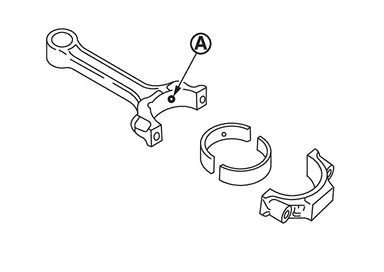
Ensure the oil hole
on connecting rod and that on the corresponding bearing are aligned.
Install piston and connecting rod assembly to crankshaft.
Position crankshaft pin corresponding to connecting rod to be installed onto the bottom dead center.
Apply engine oil sufficiently to the cylinder bore, piston and crankshaft pin journal.
Match the cylinder position with the cylinder number on connecting rod to install.
Be sure that front mark on piston crown is facing the front of the engine.
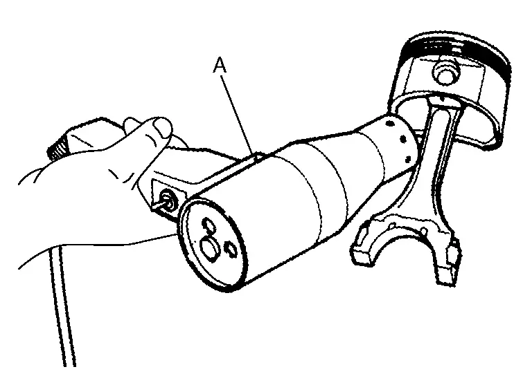
Using a piston ring compressor [SST: EM03470000 (NI-8037)] (A) or suitable tool, install piston with the front mark on the piston crown facing the front of the engine.
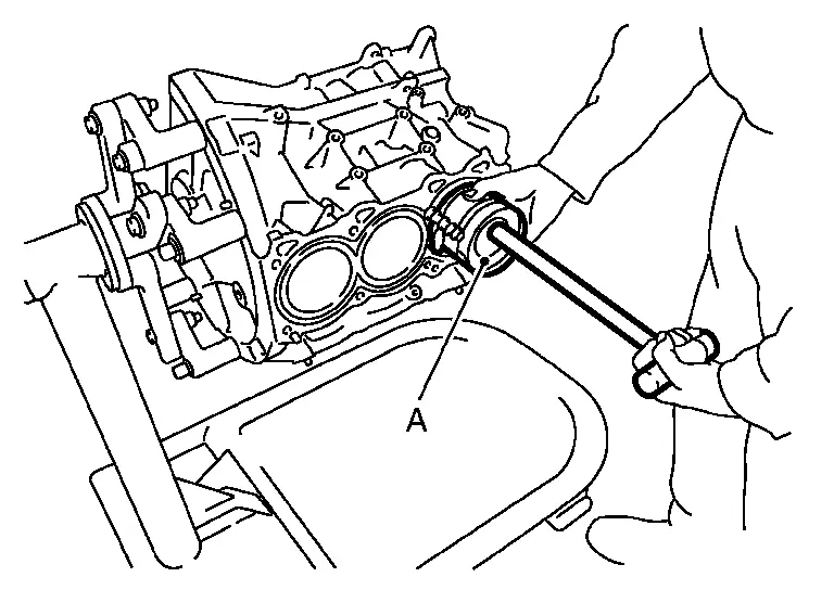
CAUTION:
Never damage the cylinder wall and crankshaft pin, resulting from an interference of the connecting rod big end.
Install connecting rod bearing cap.
Match the stamped cylinder number marks on connecting rod with those on connecting rod bearing cap to install.
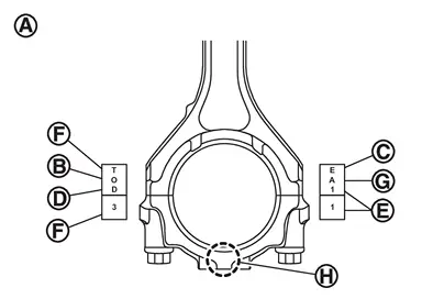
: Sample codes : Small-end diameter grade : Big-end diameter grade : Weight grade : Cylinder No. : Management code 
: Management code Be sure that front mark
 on connecting rod bearing cap is facing the front of the engine.
Tighten connecting rod bolt as follows:Inspect the outer diameter of connecting rod bolt. Refer to Inspection. Apply engine oil to the threads and seats of connecting rod bolts. Tighten connecting rod bolts.
| : 28.4 N·m (2.9 kg-m, 21 ft-lb) |
 : 0 N·m (0 kg-m, 0 in-lb) : 0 N·m (0 kg-m, 0 in-lb) |
| : 24.5 N·m (2.5 kg-m, 18 ft-lb) |
CAUTION:
Always use the angle wrench [SST: KV10112100 (BT-8653-A)] (A). Never make judgment by visual inspection.
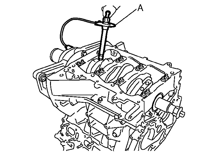
After tightening connecting rod bolts, check that crankshaft rotates smoothly.
Check the connecting rod side clearance. Refer to Inspection.
Install oil pump.Refer to Removal and Installation.
Install baffle plate.Refer to Disassembly and Assembly.
Install oil strainer.Refer to Disassembly and Assembly.
Install knock sensors .
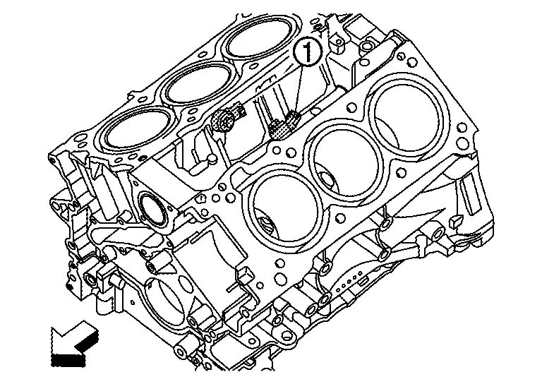
| : Engine front |
Install knock sensor so that connector faces the rear of the engine.
After installing knock sensor, connect harness connector, and lay it out to rear of the engine.
CAUTION:
Never tighten mounting bolts while holding connector.
If any impact by dropping is applied to knock sensor, replace it with new one.
NOTE:
Check that there is no foreign material on the cylinder block mating surface and the back surface of knock sensor.
Check that knock sensor does not interfere with other parts.
Install new rear oil seal. Refer to Removal & Installation.
Apply new engine oil to both oil seal lip and dust seal lip.
 Exploded View
Sub harness Knock sensor Cylinder block Oil gallery cover Gasket Plug O-ring Rear oil seal Oil jet Main bearing (upper) Crankshaft Thrust bearing Main bearing (lower) Plug Gasket Lowe ...
 Inspection
CRANKSHAFT END PLAY
Measure the clearance between thrust bearings and crankshaft arm when crankshaft is moved fully forward or backward with a dial indicator.
Standard and limit : Refer to Cylinder ...
Other materials:
Key Points in Actual Repair Work
CAUTION:
Illustration shows a badly damaged side member for clarity. Badly damaged or kinked side rails must always be replaced.
(1) STRETCHING SHRUNK PORTIONS
The repair of a bent closed cross-sectional structure, such as a side member, is done by clamping the surface of the bent-in side and pullin ...
Inspection
INSPECTION AFTER REMOVAL
Appearance
Check the following items, and replace the part if necessary.
Upper link and bushing for deformation, cracks or damage.
Ball joint boot for cracks or other damage, and also for grease leakage.
Ball Joint Inspection
Manually move ball stud to confirm it moves smoo ...
Front, front central seat-mounted side-impact supplemental air bag and roof-mounted
curtain side-impact and rollover supplemental air bag systems
*: if so equipped
In the Nissan Armada, the supplemental side-impact and curtain air bag systems
are engineered to provide enhanced protection for occupants during side collisions
and rollover events. These systems work together with seat belts to form a comprehensive
safety network.
The ...

0.0063