Additional Service When Replacing 8ch Can Gateway
Description
When replacing the 8CH gateway, perform "Procedure before replacing" and "Procedure after replacing". Refer to Work Procedure.
CAUTION:
-
Never reuse the parts which has been dropped
-
Dispose 8CH CAN gateway which is paired with Intelligent Key unit as it cannot reuse to other vehicle.
Work Procedure
BEFORE REPLACEMENT
Perform control unit information saving procedure before replacing 8CH CAN gateway
 NOTE:
NOTE:
It is necessary to save the control unit information to CONSULT to migrate the 8CH CAN gateway data after replacing. Refer to CONSULT manual for detail.
SAVING CONTROL UNIT INFORMATION
With CONSULT
-
Ignition switch OFF.
-
Reconnect all of the disconnected harness connector.
-
Ignition switch ON.
-
Select “Replace ECU� mode of “8ch CAN GATEWAY 2�.
-
Follow the steps displayed in CONSULT.
NOTE:
Control unit information will be automatically saved in CONSULT.
>>
Replace 8CH CAN gateway. Refer to Removal & Installation.
AFTER REPLACEMENT
Perform following procedure after replacing the 8CH CAN gateway
-
Programming
-
C/U setting
-
Writing the control unit information
-
Register of vehicle identification number
-
8CH CAN gateway and Intelligent Key unit pairing
NOTE:
Connect the CONSULT to the network and download the component data. And CONSULT writes the vehicle specification to 8CH CAN gateway. Refer to the CONSULT manual for detail.
PERFORM REPLACE ECU
With CONSULT
-
Select “Replace ECU� mode of “8ch CAN GATEWAY 2�.
-
Follow the steps displayed in CONSULT.
CAUTION:
Keep the following condition when working on the steps.
-
Ignition switch ON.
-
Turn OFF all of the electric load.
-
Never depress the brake pedal
-
Battery voltage must be between 12 to 13.5V (Check the battery voltage displayed on the CONSULT.)
NOTE:
Programming, C/U setting and writing control unit information will be automatically performed.
-
>>
GO TO 2.
VIN REGISTRATION WRITING
With CONSULT
-
Select “Work support� mode of “8ch CAN GATEWAY 2� using CONSULT.
-
Select “WRITE VIN DATA�
-
Follow the instruction displayed in CONSULT.
>>
GO TO 3.
PAIRING OF 8CH CAN GATEWAY AND INTELLIGENT KEY UNIT
With CONSULT
Select “Quick Maintenance� → “Immobilizer� → “CGW Replacement� and follow the instruction displayed in CONSULT.
>>
GO TO 4.
PERFORM THE SELF-DIAGNOSIS
With CONSULT
-
Erase all self-diagnosis results using CONSULT.
-
Ignition switch OFF, and leave the vehicle with the driver's side door open. and wait for 2 minutes or more.
NOTE:
Since the auto ACC function causes the accessory power to be turned ON, do not perform any vehicle operation including locking the doors or opening and closing of the doors during the standby state. Refer to System Description.
-
Ignition switch ON and wait for 62 seconds or more.
-
Perform "All DTC result" using CONSULT.
CAN communication DTCs detected?
YES>>Perform trouble diagnosis procedure for CAN communication system. Refer to Trouble Diagnosis Flow Chart.
NO>>INSPECTION END
8ch Can Gateway
Removal & Installation
NOTE:
Perform ADDITIONAL SERVICE WHEN REPLACING 8CH CAN GATEWAY. Refer to Description.
REMOVAL
Remove instrument lower panel LH. Refer to Removal and Installation.
Remove front center console body assembly. Refer to Removal and Installation.
Remove center instrument lower panel. Refer to Removal and Installation.
Remove 8CH CAN gateway  harness connectors
  .
.
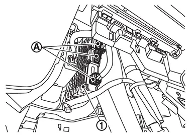
Pull out 8CH CAN gateway from the steering member.
INSTALLATION
Install in the reverse order of removal.
Other materials
9at: Ge9r01a Tools and Preparation
Preparation
Special Service Tool
The actual shape of the tools may differ from those illustrated here.
Tool number
(TechMate No.)
Tool name
Description
—
(NI-52940)
Transmission jack adaptor
Removing and installing A/T assembly
—
(NI-52972–2)
OFT position change wrench
Remov ...
Drive Pinion
Exploded View
Drive pinion lock nut
Companion flange
Front oil seal
Pinion front bearing
Collapsible spacer
Gasket
Filler plug
Drain plug
Mounting insulator
Gear carrier
Mounting insulator
Breather connector
Side shaft bearing
Snap ring
Snap ring
S ...
Mac Kye Writing
Description
When replacing chassis control module, it is necessary to write MAC key to chassis control module. Write MAC key to chassis control module according to "MAC Key writing" procedure of "CONSULT Operation Manual". Refer to Work Procedure.CAUTION:
During MAC key writing, maintain the followi ...