Precaution for Supplemental Restraint System (SRS) "AIR BAG" and "SEAT BELT PRE-TENSIONER"
The Supplemental Restraint System such as “AIR BAG� and “SEAT BELT PRE-TENSIONER�, used along with a front seat belt, helps to reduce the risk or severity of injury to the driver and front passenger for certain types of collision.
Information necessary to service the system safely is included in the “SRS AIR BAG� and “SEAT BELT� of this Service Manual.
WARNING:
Always observe the following items for preventing accidental activation.
-
To avoid rendering the SRS inoperative, which could increase the risk of personal injury or death in the event of a collision that would result in air bag inflation, it is recommended that all maintenance and repair be performed by an authorized NISSAN/INFINITI dealer.
-
Improper repair, including incorrect removal and installation of the SRS, can lead to personal injury caused by unintentional activation of the system. For removal of Spiral Cable and Air Bag Module, see “SRS AIR BAG�.
-
Never use electrical test equipment on any circuit related to the SRS unless instructed to in this Service Manual. SRS wiring harnesses can be identified by yellow and/or orange harnesses or harness connectors.
PRECAUTIONS WHEN USING POWER TOOLS (AIR OR ELECTRIC) AND HAMMERS
WARNING:
Always observe the following items for preventing accidental activation.
-
When using air or electric power tools or hammers, always switch the ignition/power switch OFF, disconnect the 12V battery or batteries, and wait at least 3 minutes before performing any service.
Precautions for Removing Battery Terminal
-
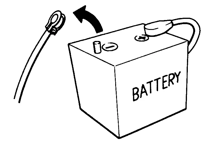
When disconnecting the 12V battery terminal, turn off the ACC power before disconnecting the 12V battery terminal, observing “How to disconnect 12V battery terminal� described below.
 NOTE:
NOTE:
Some ECUs operate for a certain fixed time even after ignition switch is turned OFF and ignition power supply is stopped. If the battery terminal is disconnected before ECU stops, accidental DTC detection or ECU data damage may occur.
-
For Nissan Armada vehicles with the 2-batteries, be sure to connect the main battery and the sub battery before turning ON the ignition switch.
NOTE:
If the ignition switch is turned ON with any one of the terminals of main battery and sub battery disconnected, then DTC may be detected.
-
After installing the 12V battery, always check "Self Diagnosis Result" of all ECUs and erase DTC.
NOTE:
The removal of 12V battery may cause a DTC detection error.
HOW TO DISCONNECT 12V BATTERY TERMINAL
Disconnect 12V battery terminal according to instruction described below.
-
Open the hood.
-
Turn ignition switch to the ON position.
-
Turn ignition switch to the OFF position with the driver side door opened.
-
Get out of the vehicle and close the driver side door.
-
Wait at least 3 minutes. For vehicle with the engine listed below, remove the battery terminal after a lapse of the specified time.
BR08DE : 4 minutes R9N engine : 12 minutes BR10DE : 12 minutes V9X engine : 4 minutes D4D engine : 20 minutes YD25DDTi : 2 minutes HR09DET : 12 minutes YS23DDT : 4 minutes HR10DDT : 12 minutes YS23DDTT : 4 minutes HR10DET : 12 minutes ZD30DDTi : 60 seconds HR13DDT : 12 minutes ZD30DDTT : 60 seconds HRA2DDT : 12 minutes K9K engine : 4 minutes M9R engine : 4 minutes R9M engine : 4 minutes CAUTION:
While waiting, never operate the vehicle such as locking, opening, and closing doors. Violation of this caution results in the activation of ACC power supply according to the Auto ACC function.
-
Remove 12V battery terminal.
CAUTION:
After installing 12V battery, always check self-diagnosis results of all ECUs and erase DTC.
PRECAUTIONS FOR HOOD OPEN IDLE UP: Precautions
ECM controls to increase the idling speed when the hood is opened. Refer to Inspection.
When checking the idling speed during inspection and maintenance, perform "Hood open idle up cancel mode". Refer to Removal and Installation.
Precautions for Harness Repair
-
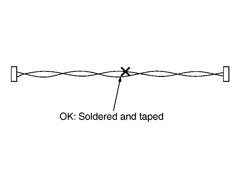
Solder the repaired area and wrap tape around the soldered area.
 NOTE:
NOTE:
A fray of twisted lines must be within 110 mm (4.33 in).
-
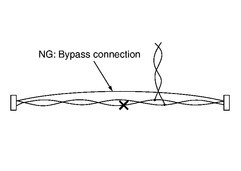
Bypass connection is never allowed at the repaired area.
 NOTE:
NOTE:
Bypass connection may cause CAN communication error. The spliced wire becomes separated and the characteristics of twisted line are lost.
-
Replace the applicable harness as an assembly if error is detected on the shield lines of CAN communication line.
Precaution for Automatic Brake Hold
-
Do not disassemble chassis control module.
-
Do not use any parts that have been dropped.
-
Do not perform active test during driving.
-
Do not operate automatic brake hold function on a steep slope or a slippery road. (The vehicle may move even when automatic brake hold function is applied.)
-
When the stopped condition of the vehicle cannot be maintained by automatic brake hold function, depress brake pedal to maintain the stopped condition.
-
Master warning lamp (yellow) illuminates if a malfunction occurs in automatic brake hold function. A pop-up screen also appears. Refer to Chassis Control Warning.
-
When the vehicle is moved or may start moving while automatic brake hold function is being applied,master warning lamp (red) illuminates, and a warning chime sounds at the same time. A pop-up screen also appears. Refer to Automatic Brake Hold Warning.
-
Be sure to deactivate automatic brake hold function when using a car wash machine, towing your vehicle or overloaded.
-
Automatic brake hold function will not be activated when the vehicle is in the 4L position.
-
If 4WD shift switch is shifted to 4L position when automatic brake hold function is activated, the braking force of automatic brake hold function will be released.
-
When parking the vehicle, with shift position is in P and apply electric parking brake.
-
When getting on the vehicle or when loading/unloading a cargo, with shift position is in P and apply electric parking brake.
-
When VDC warning lamp, brake system warning lamp, or electric parking brake warning lamp is illuminated, or chassis control warning (automatic brake hold function) message appears, automatic brake hold function does not operate.
-
Automatic brake hold function retains the last state until the driver changes the option even if the ignition switch OFF.
-
Automatic brake hold function is operated by applying sufficient braking force to hold the vehicle in its place, so there are cases when this hold function is maintained even if the accelerator pedal is depressed. In this situation, it is advised to depress the brake pedal first, then to turn OFF automatic brake hold switch. This will cancel the hold function.
-
While automatic brake hold function is being applied, the system may apply the brakes to maintain the stopped condition of the vehicle.
-
At this time, a operating noise may be generated. These are not symptoms of malfunctions and indicate normal operating conditions.
-
If the switch indicator does not illuminate after operating automatic brake hold switch, inspect brake control system and electric parking brake system in addition to automatic brake hold function.
-
If parts of related to automatic brake hold function are replaced, check automatic brake hold switch indicator can turns ON/OFF.
-
Parts of related to automatic brake hold function: Refer to System Description.
Other materials
Parking Brake Switch
Removal and Installation
REMOVALRemove the instrument lower panel LH. Refer to Removal and Installation.
Remove parking brake switch mounting screws , and then remove parking brake switch .
: Instrument lower panel LH
INSTALLATIONInstall in the reverse order of removal. ...
High-Pressure Pipe
Removal and Installation
WARNING:
Jacking up or lifting up the vehicle may the vehicle height to go down which cause a personal injury and/or damage to the air suspension component parts. Refer to Precaution for when Jacking and Lifting Up the vehicle with Electronic Air Suspension System (With ele ...
Precautions
Precautions for Removing Battery Terminal
When disconnecting the 12V battery terminal, turn off the ACC power before disconnecting the 12V battery terminal, observing “How to disconnect 12V battery terminal� described below.
NOTE:
Some ECUs operate for a certain fixed time even after ignit ...