
Nissan Armada 2025-2026 Service and Repair Manual: Precautions for Body Repair
WARNING:
WARNING:
The repair information in this section is intended for trained body repair technicians who have attained a high level of skill and experience (e.g. ASE Collision Repair Certification, I-CAR Professional Development Program [PDP] training, etc.) in repairing collision damaged vehicles using appropriate tools and equipment. Performing repairs without the proper training, tools or equipment could damage the vehicle or cause personal injury or death to you or others.
The information in this Body Repair Manual is a guideline for repairing collision damaged vehicles. However, this information cannot cover all possible ways that a vehicle can be damaged. As such, the body repair technician is responsible for making sure that the repair does not affect the structural integrity or safety of the vehicle. Improper repair of a damaged vehicle may result in a collision, property damage, personal injury or death.
Nissan recommends using only new genuine Nissan replacement body parts. Use of used, salvaged or aftermarket body parts is not recommended by Nissan. Non-genuine Nissan components may affect the vehicle's structural integrity and crash safety performance, which could result in serious personal injury or death in an accident.
Technicians are encouraged to read the Body Repair Manual (Fundamentals) in order to ensure that the original functions and quality of the vehicle are maintained. The Body Repair Manual (Fundamentals) contains additional information, including cautions and warnings, that are not including in this manual. Technicians should refer to both manuals to ensure proper repair.
Please note that this information is prepared for worldwide usage, and as such, certain procedures might not apply in some regions or countries.
The symbols used in this section for welding operations are shown below.
| Symbol marks | Description | |
|---|---|---|
| ″Number″ | ″Number″ after symbol mark is the total number of welds to apply. Example 1:  ″1″× 20 (0.79) = 1 MIG seam weld by length 20 mm (0.79 in). ″1″× 20 (0.79) = 1 MIG seam weld by length 20 mm (0.79 in). | |
| 2-panel spot weld |
|
| 3-panel spot weld | |
| MIG plug weld |
|
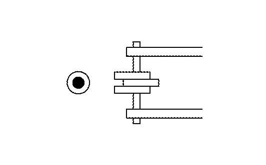
For 3-panel plug weld method
| ||
| MIG seam weld / Point weld |
|
| Rivet |
|
 ″4″A = 4 MIG plug welds for 3-panel plug weld method.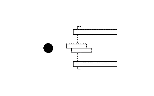
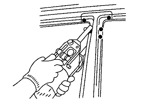
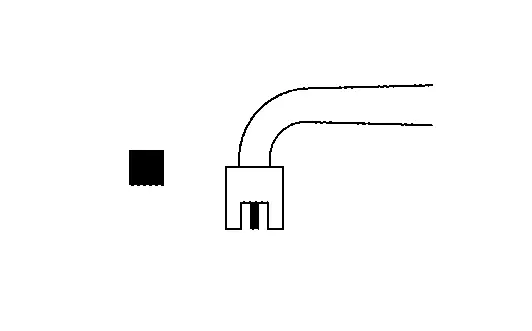
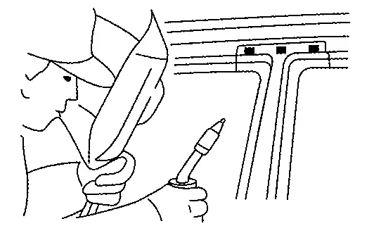
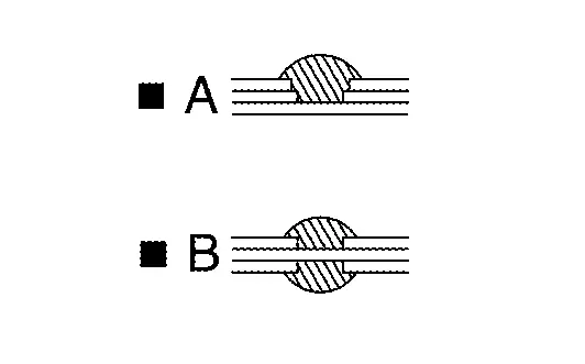
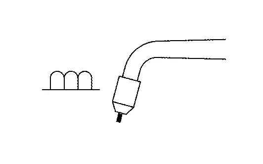
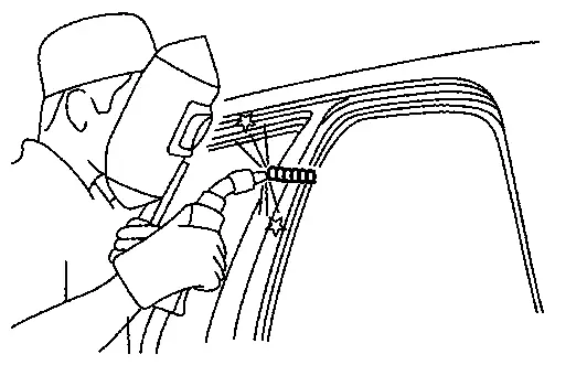
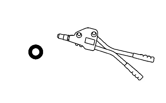
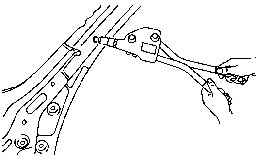
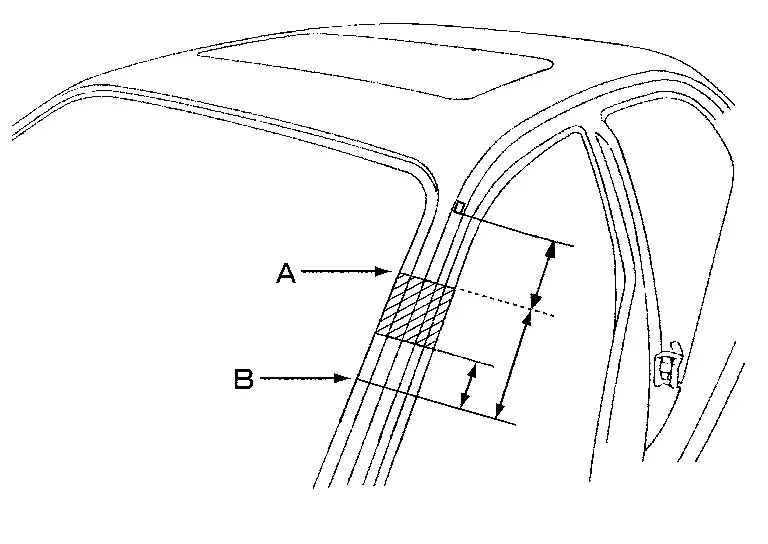
Front pillar butt joint can be determined anywhere within shaded area as shown in the figure. The best location for the butt joint is at position A due to the construction of the vehicle.
Determine cutting position and record distance from the locating indent. Use this distance when cutting the service part. Cut outer front pillar over 60 mm (2.36 in) above the inner front pillar cut position.
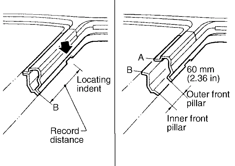
Prepare a cutting jig to make outer pillar easier to cut. Also, this will permit the service part to be accurately cut at the joint position.
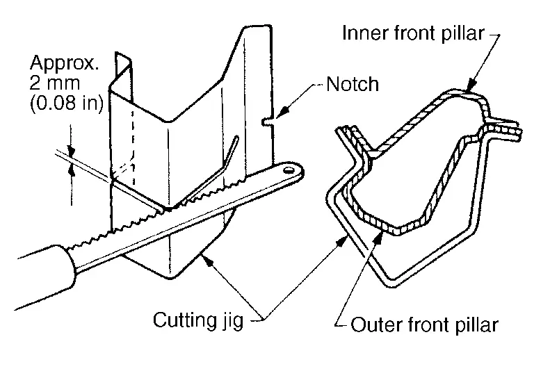
An example of cutting operation using a cutting jig is as per the following.
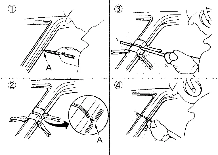
Mark cutting lines.
A: Cut position of outer pillar
B: Cut position of inner pillar
Align cutting line with notch on jig. Clamp jig to pillar.
Cut outer pillar along groove of jig (at position A).
Remove jig and cut remaining portions.
Cut inner pillar at position B in same manner.

 Welding of Ultra High Strength Steel
SPOT WELDING
Spot welding is limited to ultra high strength steel (tensile strength: 980 MPa) according to the welding conditions listed below.
CAUTION:
If the below welding conditions cannot be met, ...
Other materials:
Diagnosis Procedure
INTELLIGENT REAR VIEW MIRROR FUNCTIONAL INSPECTION
Ignition switch ON.
Check the intelligent rear view mirror system is operating normally after setting power supply lever of intelligent rear view mirror lower part to ON.
Is the inspection result normal?
YES>>
GO TO 3.
NO>>
GO TO 2.
I ...
Exploded View
REMOVAL
Propeller shaft assembly
: Vehicle front : N·m (kg-m, ft-lb) : Always replace after every disassembly.
DISASSEMBLY
Snap ring Journal bearing Journal Sleeve yoke Propeller shaft tube Flange yoke
: Vehicle front : Always replace after every disassembly. : Select with proper thickn ...
Inspection
INSPECTION AFTER REMOVAL
When turn the shaft in direction , check returning to direction by spring power.
CAUTION:
The maximum turning force shall be 5 N·m (0.51 kg-m, 44 in-lb).
When turn the shaft in direction , check locking the shaft. INSPECTION AFTER INSTALLATION
ADJUSTMENT AFTER INSTALLATIO ...

0.0063