Removal and Installation
CAUTION:
-
Perform work with 2 workers, because it is heavy weight.
-
Support door with a proper material and use protective tape or shop cloth to protect door and body from falling and damage when removing and installing door assembly.
REMOVAL
Remove rear door harness grommet from vehicle body, and then pull out rear door harness and disconnect rear door harness connector.
Remove rear door check link mounting bolt of vehicle body side.
Support rear door assembly with a proper material to prevent it from falling.
WARNING:
Injury may occur if door assembly is not supported with a proper material when removing rear door assembly.
Remove rear door hinge mounting nuts, and then remove rear door assembly.
INSTALLATION
Note the following items, and then install in the reverse order of removal.
CAUTION:
-
Before installation, apply anticorrosive agent onto the mounting surface.
-
When installation, perform the fitting adjustment. Refer to Adjustment.
-
After installation, apply touch-up paint (the body color) onto the head of rear door hinge mounting nuts.
-
After installation, check the open/close operation. Refer to Inspection.
-
After installation, apply anticorrosive around the nuts to prevent rust.
Inspection
Open and close rear door. Check that rear door hinge and rear door check link rotation portion moves smoothly.
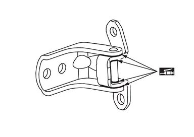
Check rear door hinge rotating part for lubrication condition. Apply body grease if necessary.
 |
: Body grease |
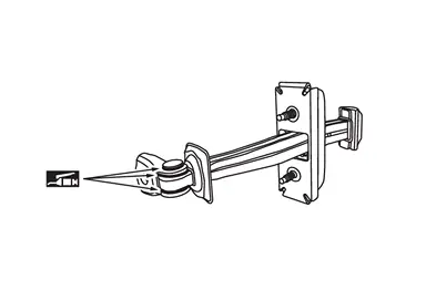
Check rear door check link rotating part for lubrication condition. Apply body grease if necessary.
|
: Body grease |
Adjustment
FITTING ADJUSTMENT
Fitting Adjustment Standard Dimension
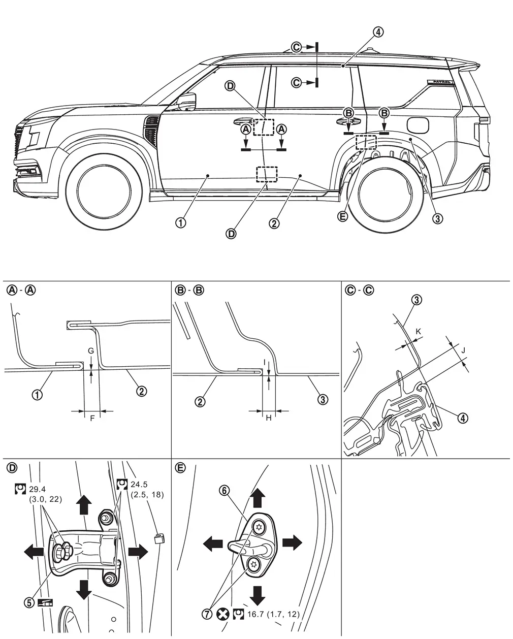
 |
Front door panel |  |
Rear door panel |  |
Body side outer |
 |
Rear door sash molding |  |
Rear door hinge |  |
Rear door striker |
 |
TORX bolt | ||||
 |
: Always replace after every disassembly. | ||||
 |
: N·m (kg-m, ft-lb) | ||||
|
: Body grease | ||||
Unit: mm [in]
| Portion | Standard | |||
|---|---|---|---|---|
| Front door panel – Rear door panel |  – – |
F | Clearance |
4.5 ± 1.0 [0.177 ± 0.039] |
| G | Surface height |
0.0 ± 1.0 [0.000 ± 0.039] |
||
| Rear door panel – Body side outer |  – – |
H | Clearance |
4.5 ± 1.0 [0.177 ± 0.039] |
| I | Surface height |
0.0 ± 1.0 [0.000 ± 0.039] |
||
| Rear door sash molding – Body side outer |  – – |
J | Clearance |
7.3 ± 1.8 [0.287 ± 0.071] |
| K | Surface height |
1.0 ± 1.7 [0.039 ± 0.067] |
||
Check the clearance and surface height between rear door and each part by visually and touching.
If the clearance and the surface height are out of specification, adjust them according to the procedures shown below.
Fitting Adjustment Procedure
Loosen rear door hinge mounting nuts.
Adjust the surface height of rear door according to the fitting adjustment standard dimension by moving rear door panel.
Tighten rear door hinge mounting nuts to the specified torque.
CAUTION:
After installation, apply touch-up paint (the body color) onto the head of hinge mounting nuts.
Loosen rear door hinge mounting bolts.
Adjust the clearance of rear door according to the fitting adjustment standard dimension by moving rear door panel.
Tighten rear door hinge mounting bolts to the specified torque.
CAUTION:
-
After installation, apply touch-up paint (the body color) onto the head of hinge mounting bolts.
-
After installation, apply anticorrosive around the bolts and nuts to prevent rust.
REAR DOOR STRIKER ADJUSTMENT
Adjust rear door striker so that it becomes parallel with door lock insertion direction.
Other materials
NissanConnect Owner's Manual
QR code (U.S. only)
The Nissan Armada NissanConnect Owner’s Manual can be conveniently accessed by
scanning the QR code shown above (U.S. models only) or by using the printed manual
included with your vehicle.
This comprehensive Nissan Armada digital guide provides detailed explanations ...
Water Hose
Exploded View
A/T assembly
Hose clamp
A/T water hose A
A/T water hose B
Clip A
Clip B
To water pipe. Refer to Exploded View.
To oil cooling exchanger. Refer to Exploded View.
: Always replace after every disassembly.
Removal and Installation
WARNING:
Jacking up or ...
Transfer Cam Position Sensor
Exploded View
Transfer assembly
Transfer cam position sensor
: N·m (kg-m, in-lb)
Removal and Installation
WARNING:
Jacking up or lift up the vehicle may the vehicle height to go down which cause a personal injury and/or damage to the air suspe ...