
Nissan Armada 2025-2026 Service and Repair Manual: Removal & Installation
WARNING:
REMOVAL
Remove engine cover. Refer to Removal and Installation.
Disconnect battery cables from negative terminal. Refer to Removal and Installation.
Remove engine under cover front and front under cover using a power tool (commercial service tool). Refer to Removal and Installation and Removal and Installation.
Drain engine coolant. Refer to ENGINE COOLANT : Draining.
CAUTION:
Perform this step when the engine is cold.
Never spill engine coolant on drive belt.
Remove the following parts:
Drive belt. Refer to Removal & Installation.
A/C compressor belt. Refer to Removal & Installation.
Air cleaner and air duct assembly. Refer to Removal and Installation.
Inlet air duct 2. Refer to Removal and Installation.
Air inlet tube 1 and 2. Refer to Removal & Installation.
Remove radiator hose (upper and lower). Refer to RADIATOR : Removal & Installation.
Remove reservoir tank tube. Refer to RADIATOR : Exploded View.
Remove electric water pump. Refer to Removal and Installation.
Remove multi-way control valve. Refer to MULTI-WAY CONTROL VALVE : Removal & Installation.
Remove intake manifold. Refer to Removal and Installation.
Remove valve timing control cover (bank 1 and bank 2). Refer to Removal & Installation.
Remove electric intake valve timing control actuator (bank1 and bank2). Refer to Removal & Installation.
Remove rocker cover. Refer to Removal and Installation.
Remove water pump. Refer to WATER PUMP : Removal & Installation.
Remove drive belt auto-tensioner. Refer to Removal and Installation.
Remove idler pulley. Refer to Removal and Installation.
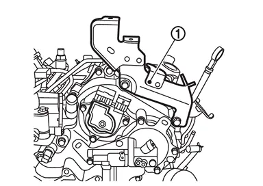
Remove engine cover bracket 1  .
.
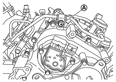
Remove fuel tube mounting bolt  .
.
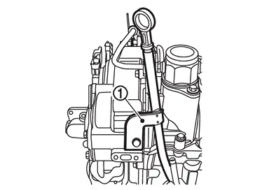
Remove oil level gauge guide .
Remove water pipe 2. Refer to Removal and Installation.
Remove alternator. Refer to Removal and Installation.
Remove oil cooler pipe 1 and 2. Refer to Removal and Installation.
Disconnect the A/T fluid cooler hose connection. Refer to Removal and Installation.
Remove A/T fluid cooler tube mounting bracket. Refer to Exploded View
Remove A/C compressor and move it to a location where it will not interfere with work.
 NOTE:
NOTE:
Do not remove high pressure flexible hose and low pressure flexible hose from A/C compressor.
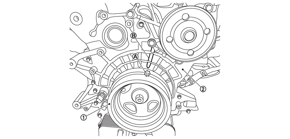
Obtain No. 1 cylinder at TDC of its compression stroke as follows:Rotate the crankshaft pulley clockwise as viewed from the front of the engine, and align the timing mark (grooved line without color) on the crankshaft pulley with  (fourth from the end on the bank 2 side) on the front cover
  .
.
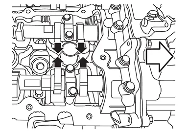
 | : Engine front |
If not, turn crankshaft one revolution (360 degrees) and align as shown in the figure.
Remove crankshaft pulley as follows:Secure crankshaft pulley with a pulley holder (A) and loosen crankshaft pulley bolt.
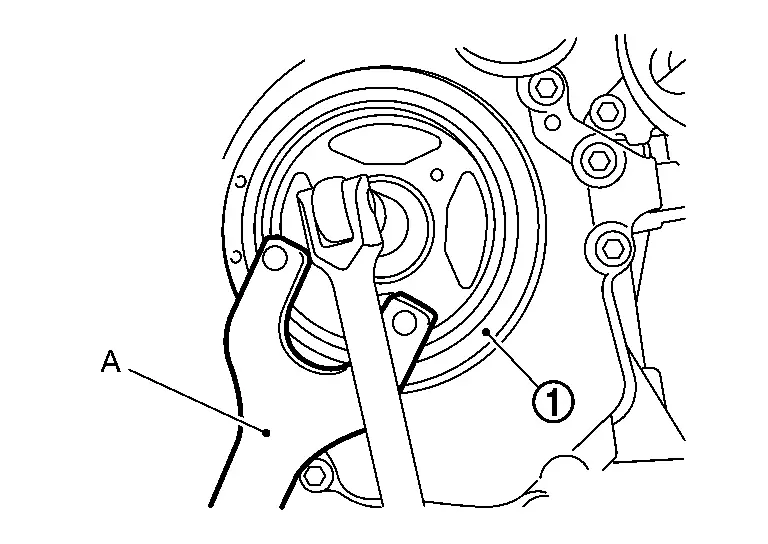
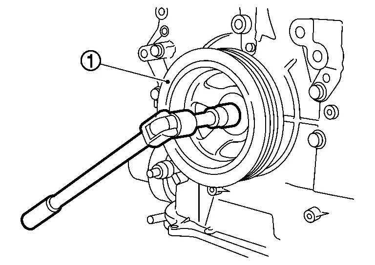
| : Crankshaft pulley |
CAUTION:
Never remove crankshaft pulley bolt as it will be used as a supporting point for suitable puller.
Place suitable puller tab on holes of crankshaft pulley, and pull crankshaft pulley through.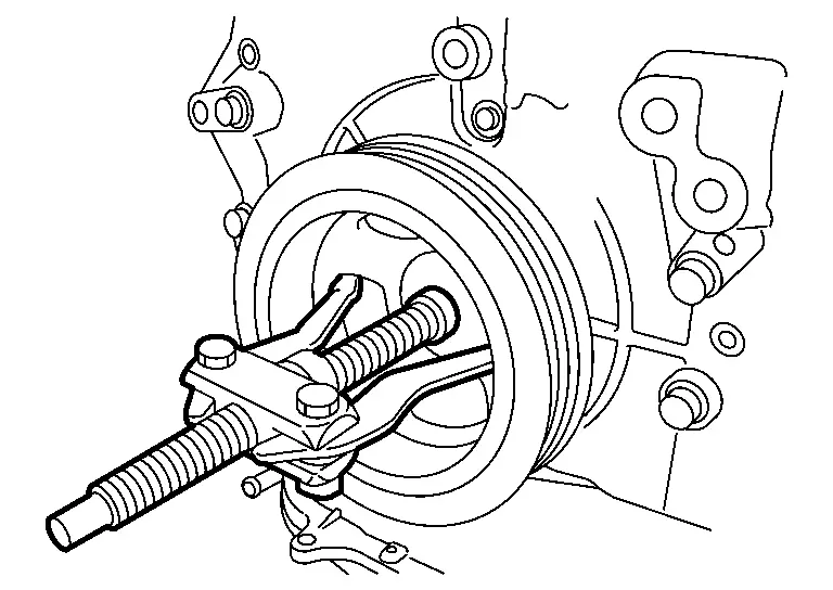
CAUTION:
Never put suitable puller tab on crankshaft pulley periphery, as this will damage internal damper.
Remove front cover as follows:Loosen mounting bolts in the order from 34 to 1 as shown in the figure.
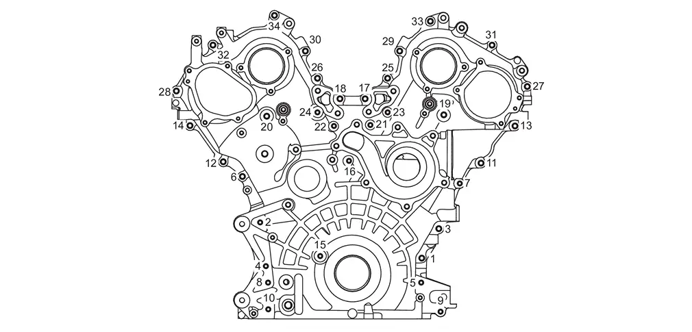
Use the seal cutter [SST: KV10111100 (NI-37228)] to cut liquid gasket for removal.
CAUTION:
Never use a screwdriver or something similar. Failure to do this may cause damage to the parts.
After removal, handle front cover carefully so it does not tilt, cant, or warp under a load.
Remove front oil seal from front cover using a suitable tool.
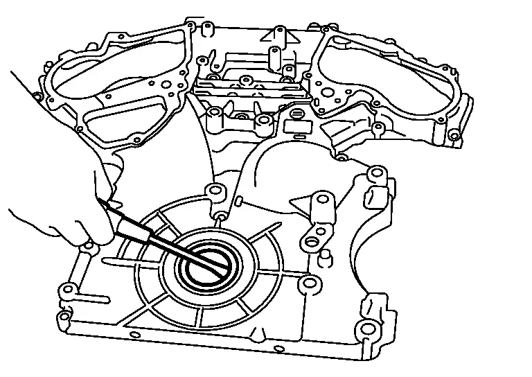
Use a screwdriver for removal.
CAUTION:
Never damage front cover.
Use a scraper to remove all traces of old liquid gasket from front cover and oil pan (upper), and liquid gasket mating surfaces.
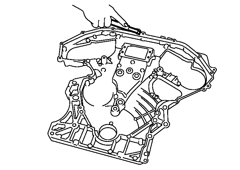
CAUTION:
Never allow gasket fragments to enter oil pan.
Remove old liquid gasket from bolt hole and thread.
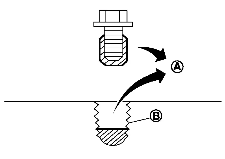
| : Remove sticking old liquid gasket |
| : Bolt hole |
INSTALLATION
Install in the reverse order of removal.
Install new O-ring(oil line) and O-ring(water line) .
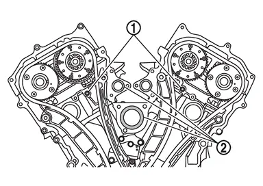
CAUTION:
Do not reuse O-rings.
Make sure the O-ring(water line) is free from separation and contamination with oil.
Apply engine coolant or water to the O-ring (water line) if necessary.
Install new front oil seal on front cover. Refer to Removal and Installation.
Install front cover as follows:
Check O-rings stay in place during installation to cylinder head and cylinder block.
back side as shown in the figure.
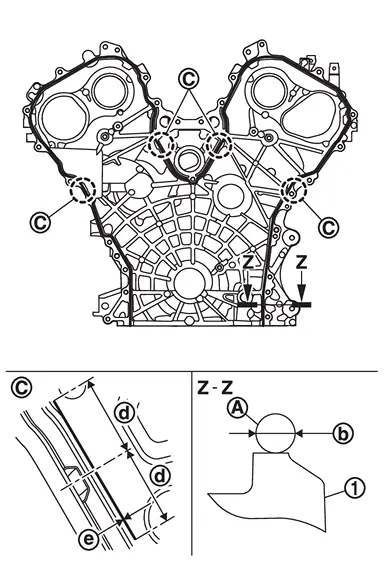
CAUTION:
When applying gasket, check and be careful with application point 
| : Liquid gasket |
 | : φ2.7 - 3.7 mm (0.106 - 0.146 in) |
 | : 15 mm (0.59 in) |
 | : φ6.0 - 7.0 mm (0.236 - 0.276 in) |
 : 11.0 N·m (1.1 kg-m, 8 ft-lb) : 11.0 N·m (1.1 kg-m, 8 ft-lb) |
There are two types of mounting bolts. Refer to the following for locating bolts.
M6 bolts [thread length: 20 mm (0.79 in)] : 1,3,6,11,12,13,14,17,18,19,20,25,26,27,28,29,30,31,32,33,34 M6 bolts [thread length: 60 mm (2.36 in)] : 2,4,5,7,8,9,10,15,16,21,22,23,24
CAUTION:
Be sure to wipe off any excessive liquid gasket leaking on surface mating with oil pan (upper).
Install rocker covers (bank 1 and bank 2). Refer to Removal and Installation.
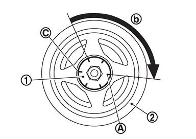
Install crankshaft pulley as follows:Fix the crankshaft in the same way as in removal. Install crankshaft pulley, taking care not to damage front oil seal.
When press-fitting crankshaft pulley with plastic hammer, tap on its center portion (not circumference).
| : 126.0 N·m(13.0 kg-m, 93 ft-lb) |
on crankshaft pulley aligning with the matching mark of crankshaft pulley bolt . Tighten the bolt 120+6 degrees (one marks) .
 Exploded View
Front cover Dowel pin Oil pressure sensor Oil temperature sensor Crankshaft pulley bolt Crankshaft pulley Front oil seal O-ring(oil line) O-ring(water line) Comply with the installation pr ...
 Timing Chain
...
Other materials:
Easy Fill Tire Alert Does Not Activate
The easy fill tire alert does not function while inflating a tire when the selectposition is in P-range with the ignition switch ON or with the engine started.
NOTE:
After starting to inflate the tire, it takes a few seconds for the easy fill tire alert to function.
If there is no response for app ...
Inspection
INSPECTION AFTER REMOVAL
Examine with eyes that there is no stain, clogging, or damage on air cleaner filter.
Remove dusts (such as dead leafs) on air cleaner filter surface and inside cleaner case.
To clean air cleaner element, blow it from intake manifold side towards air intake side to remove tra ...
Precautions for Removing Battery Terminal
With the adoption of Auto ACC function, ACC power is automatically supplied by operating the Intelligent Key or remote keyless entry or by opening/closing the driver side door. In addition, ACC power is supplied even after the ignition switch is turned to the OFF position, i.e. ACC power is supplied ...

0.006