
Nissan Armada 2025-2026 Service and Repair Manual: Removal and Installation
WARNING:
REMOVAL
CAUTION:
When removing the A/T assembly from engine, first remove the crankshaft position sensor (POS) from the A/T assembly.
Be careful not to damage sensor edge.
When replacing A/T assembly, Perform "ADDITIONAL SERVICE WHEN REPLACING TRANSMISSION ASSEMBLY". Refer to Description.
Release the parking brake.
Activate the neutral hold mode. Refer to Neutral Hold Mode Indicator.
Ignition switch OFF.
 NOTE:
NOTE:
After ignition switch OFF, confirm that the propeller shaft assembly can be turned.
Disconnect the battery cable from the negative terminal.
Remove front under cover. Refer to Removal and Installation.
Remove starter motor. Refer to Removal and Installation.
Drain engine coolant. Refer to ENGINE COOLANT : Draining.
Drain A/T fluid. Refer to Draining.
Remove water hoses from the A/T fluid warmer. Refer to Removal and Installation.
Remove A/T fluid warmer. Refer to Removal and Installation.
Remove A/T fluid cooler tubes from the A/T assembly. Refer to Removal and Installation.
Plug up openings such as the A/T fluid cooler tube holes.
Disconnect harness connector from transfer range position sensor.
Without "4L" switch (on 4WD shift switch) and differential lock system: Refer to Removal and Installation (Transfer: ATX93A).
With "4L" switch (on 4WD shift switch) and without differential lock system: Refer to Removal and Installation (Transfer: ATX93B).
With "4L" switch (on 4WD shift switch) and differential lock system: Refer to Removal and Installation (Transfer: ATX93C).
Remove A/T air breather hose from the A/T assembly. Refer to Removal and Installation.
Remove heat shield mounting bolts and remove the heat shield. Refer to Removal and Installation.
Disconnect harness connector from control valve & TCM. Refer to Removal and Installation.
Disconnect harness connector from transfer control actuator.
Remove main muffler. Refer to EXHAUST SYSTEM : Removal & Installation.
Remove rear propeller shaft. Refer to Removal and Installation.
Remove front final drive assembly. Refer to Removal and Installation.
Disconnect heated oxygen sensor harness connector and remove bracket. Refer to Removal and Installation.
Remove catalyst converter support bracket. Refer to Removal and Installation.
Remove Catalyst converter (bank 2). Refer to Removal and Installation.
Remove crankshaft position sensor. Refer to Removal and Installation.
CAUTION:
Never subject it to impact by dropping or hitting it.
Never disassemble.
Never allow metal filings, etc. to get on the sensor's front edge magnetic area.
Never place in an area affected by magnetism.
Remove rear plate cover. Refer to Exploded View.
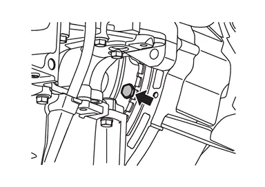
Turn crankshaft, and remove the four tightening bolts ( ) for drive plate and torque converter.
Using a suitable jack and Transmission jack adaptor (SST: NI–52940) (A), support the transmission assembly  .
.
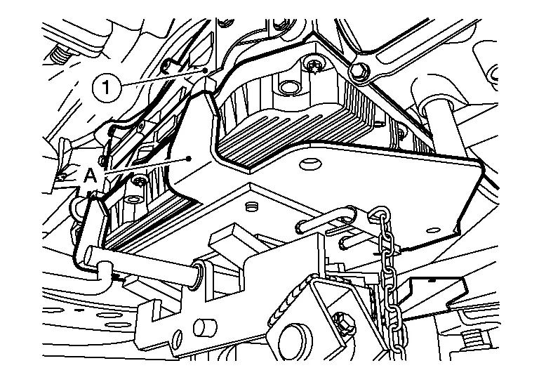
NOTE:
When installing Tool, it will support transmission assembly at locations  shown.
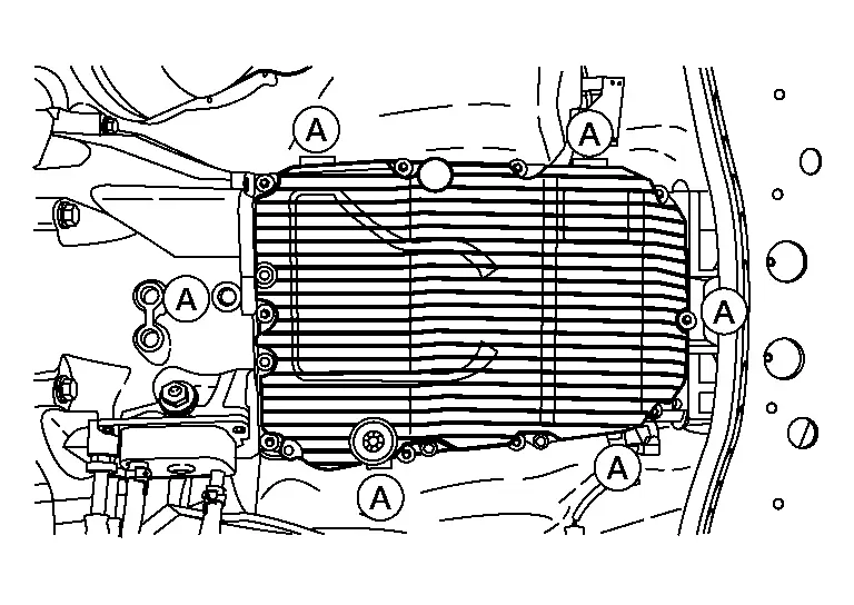
Support the transfer assembly with transmission jack.
Remove rear engine mounting cross member. Refer to Unit Removal & Installation.
Remove bolts fixing A/T assembly to engine.
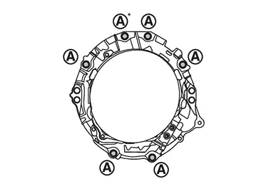
*: Tightening the bolt with bracket. Refer to Exploded View.
Remove A/T assembly with transfer assembly from the vehicle.
CAUTION:
Secure torque converter to prevent it from dropping.
Secure A/T assembly to a transmission jack.
Remove transfer assembly from transmission assembly.
INSTALLATION
Note the followings and Install in the reverse order of removal.
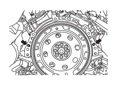
Check fitting of dowel pins (
 ).
).
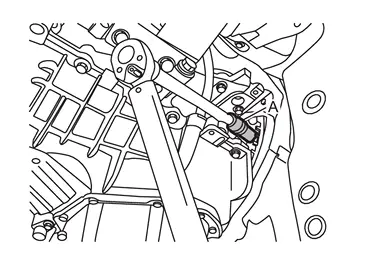
Align the positions of tightening bolts for drive plate with those of the torque converter, and temporarily tighten the bolts (
). Then, tighten the bolts with the specified torque.NOTE:When tightening bolts, tighten the bolts using universal joints (A).
CAUTION:
Rotate crankshaft clockwise (as viewed from the crankshaft pulley side).
When tightening the tightening bolts for the torque converter after fixing the crankshaft pulley bolts, be sure to confirm the tightening torque of the crankshaft pulley bolts. Refer to Removal and Installation.
Rotate crankshaft several turns and check to be sure that transmission rotates freely without binding after converter is installed to drive plate.
 Exploded View
Bracket A/T assembly Bracket Transfer assembly Bracket : N·m (kg-m, ft-lb) ...
 Inspection and Adjustment
INSPECTION BEFORE INSTALLATION
Be sure to check dimension (A) to ensure it is within the reference value limit.
B : Scale C : Straightedge
Dimension (A) : Refer to Torque Converter.
INSPECTIO ...
Other materials:
Shrinking Methods
(1) ELECTRIC WELDING MACHINE
The body panel is connected to the negative power supply terminal and the tip is connected to the positive terminal. Then, an electric current is supplied to heat the panel. The shrinking principle is the same as that of gas welding. This method features no hammering and ...
Removal and Installation
CAUTION:
Always work with 2 workers, because it is heavy weight.
REMOVAL
Remove headrest.
Slide second seat to front most position.
Remove rear side mounting bolts of second seat assembly.
Slide second seat to rear most position.
Disengage fixing pawls using a remover tool (A) according to numerica ...
Warning/indicator lights (yellow)
Anti-lock Braking System (ABS) warning light
or
In the Nissan Armada, the Anti-lock Braking System (ABS) warning light is an
essential diagnostic indicator that confirms the proper operation of the braking
assistance system. When the ignition switch is turned to the ON position, this li ...

0.0071