
Nissan Armada 2025-2026 Service and Repair Manual: Removal and Installation
WARNING:
REMOVAL
CAUTION:
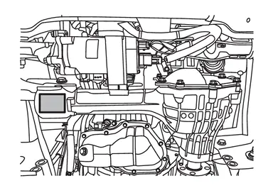
Verify identification stamp of replacement frequency put in the lower part of gear carrier to determine replacement for collapsible spacer when replacing front oil seal. Refer to “Identification stamp of replacement frequency of front oil seal�. If collapsible spacer replacement is necessary, remove final drive assembly and disassemble it to replace front oil seal and collapsible spacer. Refer to Disassembly and Assembly.
 NOTE:
NOTE:
The reuse of collapsible spacer is prohibited in principle. However, it is reusable on a one-time basis only in cases when replacing front oil seal.
Identification stamp of replacement frequency of front oil seal
The diagonally shaded area in the figure shows stamping point for replacement frequency of front oil seal.
The following table shows if collapsible spacer replacement is needed before replacing front oil seal.
When collapsible spacer replacement is required, disassemble final drive assembly to replace collapsible spacer and front oil seal. Refer to Disassembly and Assembly.
Stamp Collapsible spacer replacement No stamp Not required “0� or “0� on the far right of stamp Required “01� or “1� on the far right of stamp Not required CAUTION:
Make a stamping after replacing front oil seal.
After replacing front oil seal, make a stamping on the stamping point in accordance with the table below in order to identify replacement frequency.
CAUTION:
Make a stamping from left to right.
Stamp before stamping Stamping on the far right Stamping No stamp 0 0 “0�
(Front oil seal was replaced once.)1 01 “01�
(Collapsible spacer and front oil seal were replaced last time.)0 010 “0� is on the far right.
(Only front oil seal was replaced last time.)1 ...01 “1� is on the far right.
(Collapsible spacer and front oil seal were replaced last time.)0 ...010
Make a judgment if a collapsible spacer replacement is required.
Drain gear oil. Refer to Draining.
Remove both front drive shafts. Refer to Removal and Installation.
Remove stabilizer clamp. Refer to Removal and Installation.
Remove front propeller shaft.
Refer to Removal and Installation.
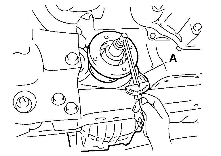
Measure the total preload with the preload gauge (A) [SST: ST3127S000 (NI-25765-A)].
NOTE:
Record the total preload torque measurement.
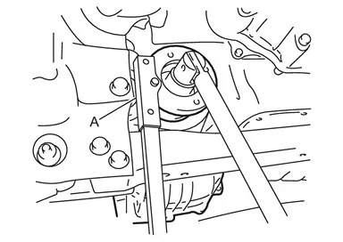
While holding companion flange with the wrench (A) (commercial service tool), remove drive pinion lock nut.
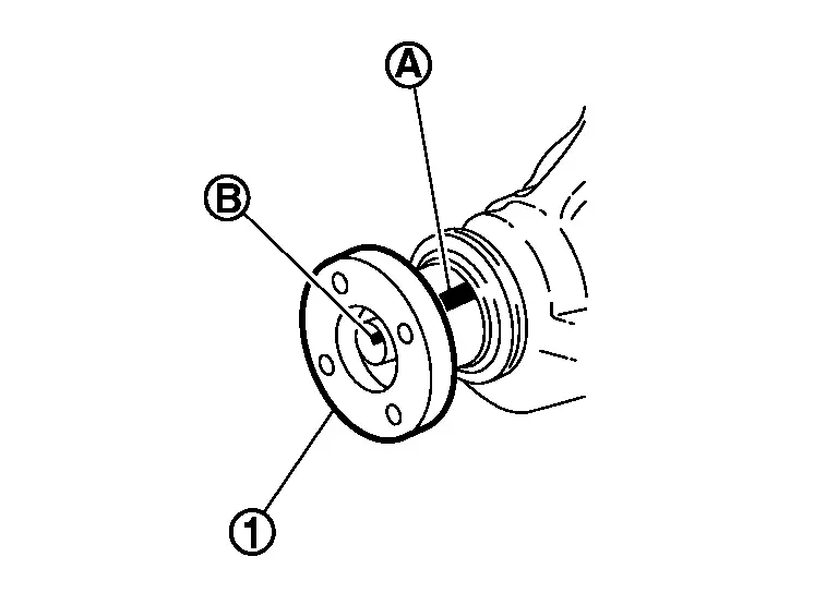
Put matching mark  on the end of the drive pinion. The matching mark should be in line with the matching mark
  on companion flange
  .
.
CAUTION:
For matching mark, use paint. Never damage companion flange and drive pinion.
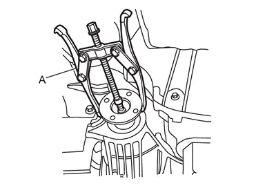
Remove companion flange using puller (A) (commercial service tool).
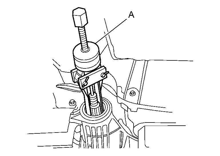
Remove front oil seal using puller (A) [SST: KV381054S0 (NI-34286)].
INSTALLATION
Drive the front oil seal in evenly using drifts (A and B).
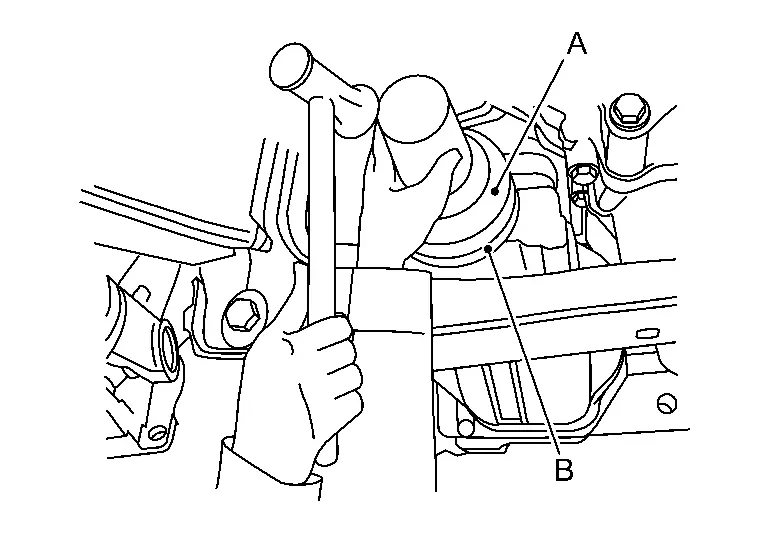
| A | : Drift [SST: ST30720000 (NI-25405)] |
| B | : Drift [SST: ST27863000 ( — )] |
CAUTION:
Never reuse oil seal.
When installing, never incline oil seal.
Check that the oil seal lip is filled up with grease.
Align the matching mark of drive pinion with the matching mark of companion flange , then install the companion flange.
Temporarily tighten drive pinion lock nut to drive pinion.
CAUTION:
Never reuse drive pinion lock nut.
While holding companion flange with the flange wrench (A) (commercial service tool), tighten drive pinion lock nut within the limits of specified torque so as to keep the bearing preload within a standard values, using preload gauge (B) [SST: ST3127S000 (NI-25765-A)].
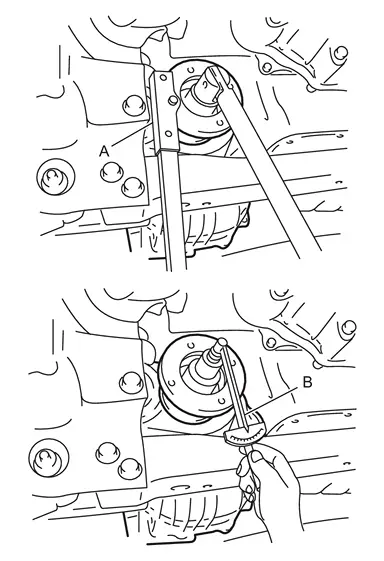
| Total preload torque | : A value that add 0.1 – 0.4 N·m (0.01 – 0.04 kg-m, 1 – 3 in-lb) to the measured value before removing. |
| Drive pinion lock nut tightening torque | : Refer to Exploded View. |
CAUTION:
Adjust to the lower limit of the drive pinion lock nut tightening torque first.
If the preload torque exceeds the specified value, replace collapsible spacer and tighten it again to adjust. Never loosen drive pinion lock nut to adjust the preload torque.
Make a stamping for identification of front oil seal replacement frequency. Refer to “Identification stamp of replacement frequency of front oil seal�.
CAUTION:
Make a stamping after replacing front oil seal.
Install front propeller shaft.
Refer to Removal and Installation.
Install both front drive shafts. Refer to Removal and Installation.
Refill gear oil to the final drive. Refer to Refilling.
Perform inspection after installation. Refer to Inspection.
 Exploded View
Drive pinion lock nut Companion flange Front oil seal Front final drive assembly : N·m (kg-m, ft-lb) : Always replace after every disassembly. ...
 Inspection
INSPECTION AFTER INSTALLATION
Check oil level and final drive for oil leakage. Refer to Inspection. ...
Other materials:
Exploded View
With ProPILOT Assist 2.1 models
Combination switch Steering angle sensor Spiral cable : Pawl
Without ProPILOT Assist 2.1 models
Combination switch Steering angle sensor Spiral cable : Pawl : Always replace after every disassembly. ...
Inspection
INSPECTION AFTER REMOVAL
Move joint up/down, left/right, and in the axial direction. Check for any rough movement or significant looseness.
Check boot for cracks or other damage, and also for grease leakage.
If a malfunction is found, disassemble drive shaft, and then replace with new one.
INSPECT ...
NVH Troubleshooting Chart
Possible cause and SUSPECTED PARTS Symptom Reference Noise Gear tooth rough × — Gear contact improper × — Tooth surfaces worn × — Backlash incorrect × — Companion flange excessive runout × — Gear oil improper × Inspection PROPELLER SHAFT × NVH of FRONT and R ...

0.0049